Graphical abstract

Sulfur compounds are one of the major problems and undesirable contaminants in the oil and gas industries. To address this issue, mercaptan removal from the gas stream in a fixed bed reactor under nanocatalyst was investigated. In this work, meso-tetrakis (4-carboxyphenyl) porphyrinatoiron (III) chloride-supported graphene oxide [GO-FeTCPP (Cl)] nanocatalyst was synthesized and adsorption of mercaptan on nanocatalyst was studied. Fourier-transform infrared spectroscopy (FT-IR), scanning electron microscopy (SEM), X-ray diffraction (XRD), BET, and Raman spectroscopy analysis were used to characterize the nanocatalyst. This experiment investigated how temperature and Gas Hour Space Velocity (GHSV) parameters affect the mercaptan removal in presence of nanocatalyst. The research results confirmed that the reaction rate improves with increasing temperature and decreasing GHSV. According to the results, at 100 °C and GHSV of 1000 h −1 , the maximum conversion (~ 96%) of reaction was reached.
Natural gas includes heavy hydrocarbon and sulfur compounds. Mercaptans among sulfur compounds are corrosive and malodorous. Thus, the removal of sulfur compounds and mercaptans is a critical issue in refining industries [ 1 ]. Various methods have been served for mercaptan removal, but heterogeneous nanocatalysts proved the most effective among catalysts for removal of mercaptan and other sulfur compounds in the gas stream [ 2 ]. Among catalysts as a support, nanocarbon structures play a productive role in improving the performance of catalysts. Graphene, as one of the carbon structures, due to it's unique characteristics such as large specific surface area, chemical and thermal stability, and high adsorption capacity is extensively applied as an effective support for heterogeneous nanocatalysts and can enhance the activity and selectivity of catalysts [ 3 , 4 – 5 ]. Metal phthalocyanines (MPcs) display a number of unparalleled features thanks to their large conjugated molecular structure which has sturdy π – π and also the covalent interactions between aromatic rings [ 6 ]. As a tetrapyrrolic aromatic macrocycle, porphyrin is characterized by a coordination site for diverse transition metals at different oxidation positions. Therefore, the electronic properties of porphyrins are dependent on both the coordinated metals and their substituents [ 7 ]. In addition, porphyrins play a crucial to catalytic oxidation or reduction reactions as well as oxygen transport. Porphyrins have predictable firm compositions and photochemical electron-tractor ability [ 8 , 9 – 10 ]. Graphene oxide (GO) through its surface functionalities such as carboxyl, epoxy functional groups, and covalent interaction is highly activated to create more active sites on nanoparticles, and also increases physical and chemical adsorption [ 11 , 12 ]. Metalloporphyrins for formation of complexes can be gathered onto the surfaces of GO by covalent interactions. GO, as a support for porphyrin complexes and metal nanoparticle, results in increased electrocatalytic activity and stability of the nanocatalyst. The incorporation of organic molecules into supported graphene sheets makes nanoscale building blocks for potential applications in organocatalysis. The reaction between strong acidic groups and the carboxylic groups of GO bring about high activity and stability of the GO-based nanocatalyst [ 13 , 14 ]. In the previous studies, carbon nanotubes (CNTs) were considered as supports for porphyrin derivatives. As high conversion of mercaptan was achieved using 10% cobalt phthalocyanine/MWCNT and 20% w (Fe) TCPP-MWCNT in the variant operating condition, we developed this method for GO as a support [ 15 , 16 ]. In this paper, we intend to use another derivative of nanocarbon structure like GO as a support for porphyrin complex. For this purpose, GO-supported meso-tetrakis (4-carboxyphenyl) porphyrinatoiron (III) chloride nanocatalyst was synthesized for the removal of mercaptan from gas streams. Also, the impact of the kinetic and operating parameters on the removal of mercaptan was investigated.
All reagents including N , N -dimethylformamide (DMF), sulfuric acid (H2SO 4 ) 90%, phosphoric acid10% (H 2 PO 4 ), potassium permanganate (KMnO 4 ), hydrochloric acid(HCI), hydrogen peroxide(H 2 O 2 ), iron(III) chloride (FeCI 3 ), sodium hydroxide (NaOH), 4-carboxy-benzaldehyde (HO 2 CC 6 H 4 CHO), pyrrole (C 4 H 5 N), propionic acid (CH 3 CH 2 COOH) and potassium hydroxide (KOH) were provided by Merck Company. Graphene oxide (GO) (size: 1–5 μm; thickness: 0.6–1.2 nm) was obtained from purified natural graphite using a modified Hummers method.
The morphology of GO and FeTCPP (Cl) and FeTCPP (Cl)-GO nanoparticles was observed using a SEM. The chemical structures of GO and FeTCPP (Cl) (before and after linking) were characterized using FT-IR and Raman spectroscopy. To determine the crystallinity of GO, FeTCPP (Cl) and FeTCPP (Cl)/GO composite, XRD was utilized. BET and BJH methods were employed to perform the specific surface area analysis, using a Micromeritics ACAP 2020 analyzer. All the samples were outgassed at 200 °C for 5 h before the measurements.
To synthesize graphene oxide, modified Hummers’ method was used. Graphite was added to a solution containing 90% sulfuric acid and 10% phosphoric acid under magnetic stirring. During stirring in the following step, potassium permanganate was slowly added to the mixture. The produced mixture was stirred for 3 days. Subsequently, the mixture was gently decanted into a vessel containing ice and hydrogen peroxide. The graphene oxide solution was washed with deionized water several times and hydrochloric acid was removed in a laboratory centrifuge. Finally, the graphene oxide was dehydrated at 80 C˚ for 24 h under vacuum conditions.
A propionic acid solution of 4-carboxy-benzaldehyde and pyrrole were refluxed for 2 h to prepare the meso-tetrakis (4-carboxyphenyl) porphyrinatoiron (III) chloride. To synthesize the FeTCPP (Cl), FeCl
3
, and TCPP reacted in
N
,
N
-dimethylformamide (DMF), a FeC1
3
solution in DMF was added to a solution of TCPP in DMF which was under magnetic stirring for 1 h, the final mixture received heat till it reached 80 °C. The DMF was removed under vacuum and the remaining was washed with deionized water and the FeTCPP was dehydrated at 100 °C under vacuum (Scheme
1
a).
Synthesis of Meso-tetrakis (4-carboxyphenyl) porphyrinatoiron (III) chloride (
a
) and structure of GO-FeTCPP (Cl) nanocatalyst (
b
)Scheme1
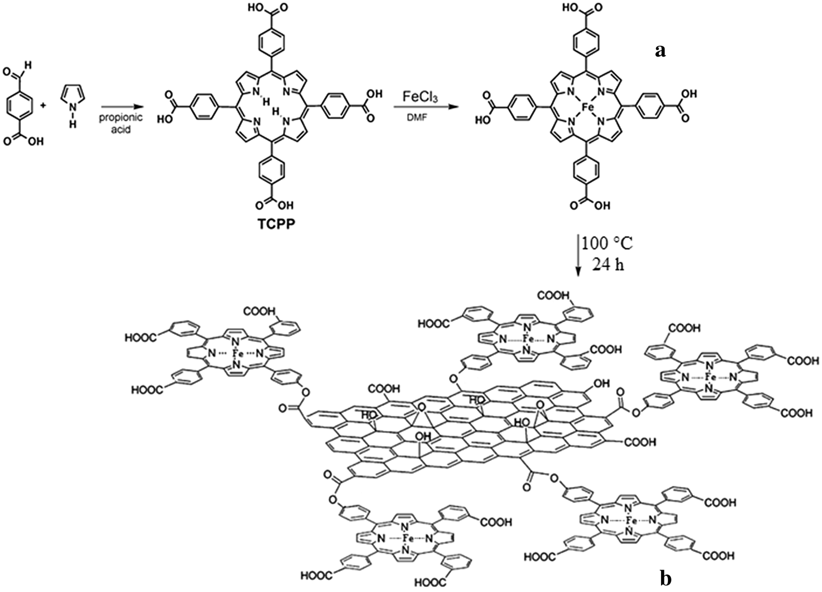
Synthesis of FeTCPP (Cl) complex supported on GO was carried out in reflux conditions. Then, graphene oxide was added to deionized water and received an ultrasonic treatment for a period of 5 min. also, (Fe) TCPP was added to the reaction mixture and was subsequently left for another 15 min. The resulting mixture was placed under reflux for 24 h at 100 °C. Then the mixture was washed with deionized water and finally was dried for 6 h at 70 °C (Scheme 1 b).
The crystalline structures of graphane (G), graphane oxide (GO), complex of meso-tetrakis (4-carboxyphenyl) porphyrinatoiron (III) chloride FeTCPP (Cl) and GO-FeTCPP (Cl) nanocatalyst can be confirmed by X-ray diffraction (XRD). As shown in Fig.
1
a, the peaks of G at 26.6°, 73.53°, and 46° are related to the crystalline structure of graphite. The natural graphite exhibited a peak at 26.6° with the basal plane spacing of
d
002
= 0.336 nm. A broad peak at 11.43° was observed for the GO due to the (001) reflection of adjacent graphene layers. Moreover, the crystalline structure of complex FeTCPP (Cl) shows peaks at about 30° and 43°. Compared to GO, the d-spacings have slightly decreased for GO-FeTCPP (Cl) in some cases, but the peak intensities for GO-FeTCPP (Cl) are still considerably low. As shown in Fig.
1
a, as a result of the reaction between the porphyrin molecules and GO, the GO-FeTCPP (Cl) nanocomposites display a (001) peak at 2
θ
= 9° (
d
-spacing = 0.95 nm), obviously lower than that of GO. The characteristic peaks of the attached catalyst were not observed clearly, which indicates the FeTCPP (Cl) complex was well dispersed on the GO as well as the peak at 2
θ
= 25.5° corresponding to the graphene nanosheets that follow functionalization of the GO sheets with FeTCPP(Cl) has incomplete recovery [
17
,
18
,
19
,
20
–
21
].
XRD patterns of G, GO, and GO-FeTCPP (Cl) (
a
), AFT-IR spectra of G, GO, and GO-FeTCPP (Cl) (
b
) and Raman spectra of G, GO, and GO-FeTCPP (Cl) (
c
)Fig. 1
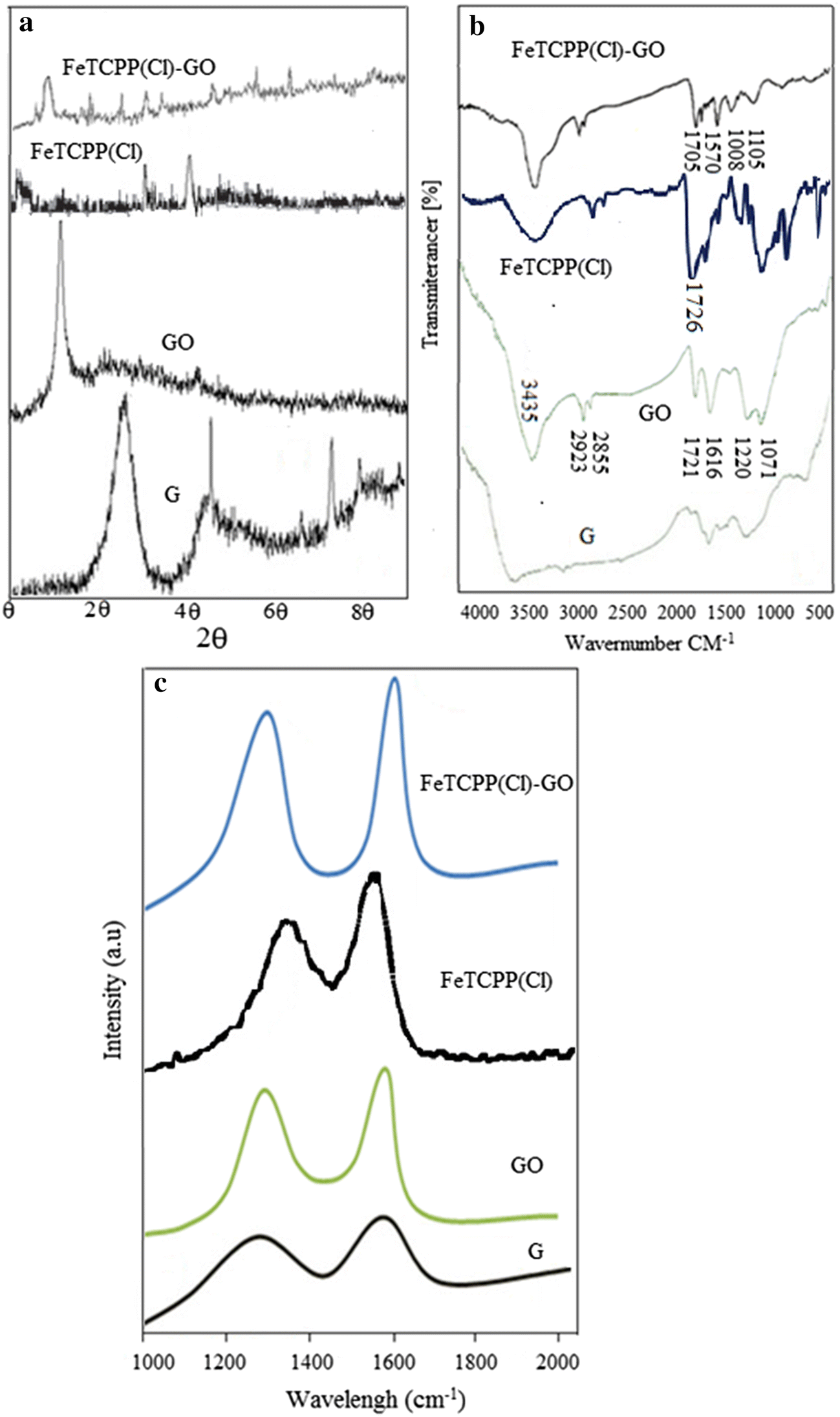
The FT–IR spectra of graphane (G), graphane oxide (GO), meso-tetrakis (4-carboxyphenyl) porphyrinatoiron (III) chloride FeTCPP (Cl) complex and [GO-FeTCPP (Cl)] nanocatalyst are shown in Fig. 1 b. The peaks at 1071, 1220 cm −1 , 1616 cm −1 , and 1721 cm −1 are accounted for by the C–O–C (epoxy), C–OH, C=C, and C=O (carbonyl and carboxylic) groups present in graphene oxide, respectively, while a stretching band at 3435 cm −1 is linked to the O–H stretching. Approximately at 2923 cm −1 and 2855 cm −1 , the absorption intensity indicated the aromatic stretching vibrations of C–H bonds of GO. Once the functionalization is done with FeTCPP (Cl), a new peak emerges at 1570 cm −1 matching the C=C vibration of porphyrins while the peak of the C–O stretching vibration moves to 1105 cm −1 . The presence of peaks at 1695 cm −1 and 1008 cm −1 is explained by the bending vibration of the C=N of the porphyrin ring and Fe–N stretching. All these points are visibly consistent with the presence of porphyrins grafted onto the GO sheets. At around 1726 cm −1 , the FeTCPP (Cl) (Fig. 1 b) shows a broad C=O stretching bond and at 995 cm −1 , the C–H stretch of pyrrole ring appeared. The shift in C=O stretch from 1726 cm −1 to 1705 cm −1 in GO-FeTCPP (Cl) confirmed the graft between FeTCPP (Cl) and GO [ 20 , 21 , 22 , 23 – 24 ].
According to Fig. 1 c, the Raman spectrum of graphite shows vibrational peaks near 1337 and 1580 cm −1 , probably because of the D and G bands, respectively. Moreover, the GO Raman spectrum shows D and G bands at 1340 cm −1 and 1591 cm −1 , respectively. Rapid increases at D and G bands are explained by the extended graphite oxidation. Degree of disorder and defect in graphite is usually estimated using the intensity ratio ( I D / I G ) of D and G bands. The higher ratio ( I D / I G ) of GO (0.79) compared with just GO is owing to additional carboxyl groups, and also GO was more disturbed than G . The band at 1557 cm −1 of porphinato complex can be attributed to the C–C stretch as well as the band at 1366 cm −1 was assigned to C–C bonds of the pyrrole rings. After the grafting of FeTCPP (Cl), the ratio of D band to 1345 cm −1 and G -band to 1601 cm −1 was increased, which could be attributed to the interruption of the conjugated structure of GO-induced by perpendicularly grafted FeTCPP (Cl) molecules. Enhancement in the D band intensity is often linked to successful attachment of FeTCPP (Cl) complex onto the GO surface. Here, the intensity ratio ( I D / I G ) increased up to 0.98 for GO-FeTCPP (Cl), a finding that is consistent with the introduction of sp 3 defects after the functionalization and a partial recovery of the graphene structure [ 20 , 21 , 25 , 26 – 27 ].
SEM images of the nanocomposites indicate a uniform coating of the GO surface with GO-FeTCPP (Cl) (Fig.
2
). The average size of particles was approximately measured at 20–50 nm by SEM images. As can be seen in Fig.
2
b, the porphyrins were successfully positioned over the entire surface of the sheetlike structure of GO in the form of closely stacked nanoparticles (as bright spots).
SEM images of GO (
a
), GO-FeTCPP (Cl) (
b
) and analysis of nitrogen adsorption–desorption (
c
)Fig. 2
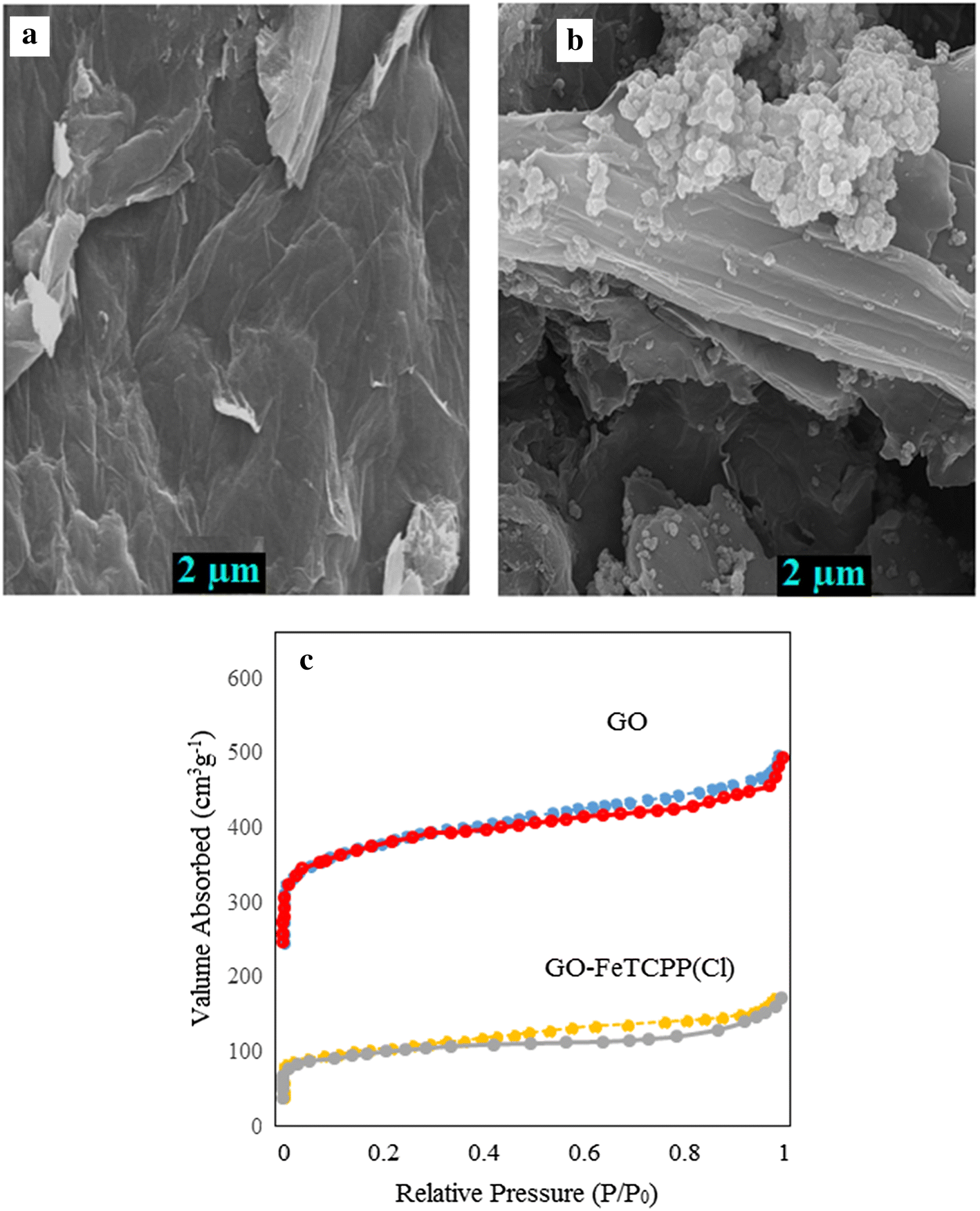
As shown in Fig.
2
c, the isotherm of GO-FeTCPP (Cl) nanocatalyst can be classified as Type I according to IUPAC classifications, which is a characteristic microporous material. The GO and GO-FeTCPP (Cl) were found to have BET surface areas of 230 m
2
/g, 60 m
2
/g, respectively. Nitrogen adsorption isotherms were used to calculate the result of BET surface area, displayed in Table
1
. The decreased surface area of FeTCPP (Cl)-GO may be due to the deposition of FeTCPP (Cl) complex on GO support [
28
].
BET surface area of GO and FeTCPP (Cl)-GO nanocatalyst Sample BET surface area (m2 g−1) Pore volume (cm3 g−1) Pore diameter (nm) FeTCPP (Cl)-GO 60 0.075 2.98 GO 230 0.824 3.01Table 1
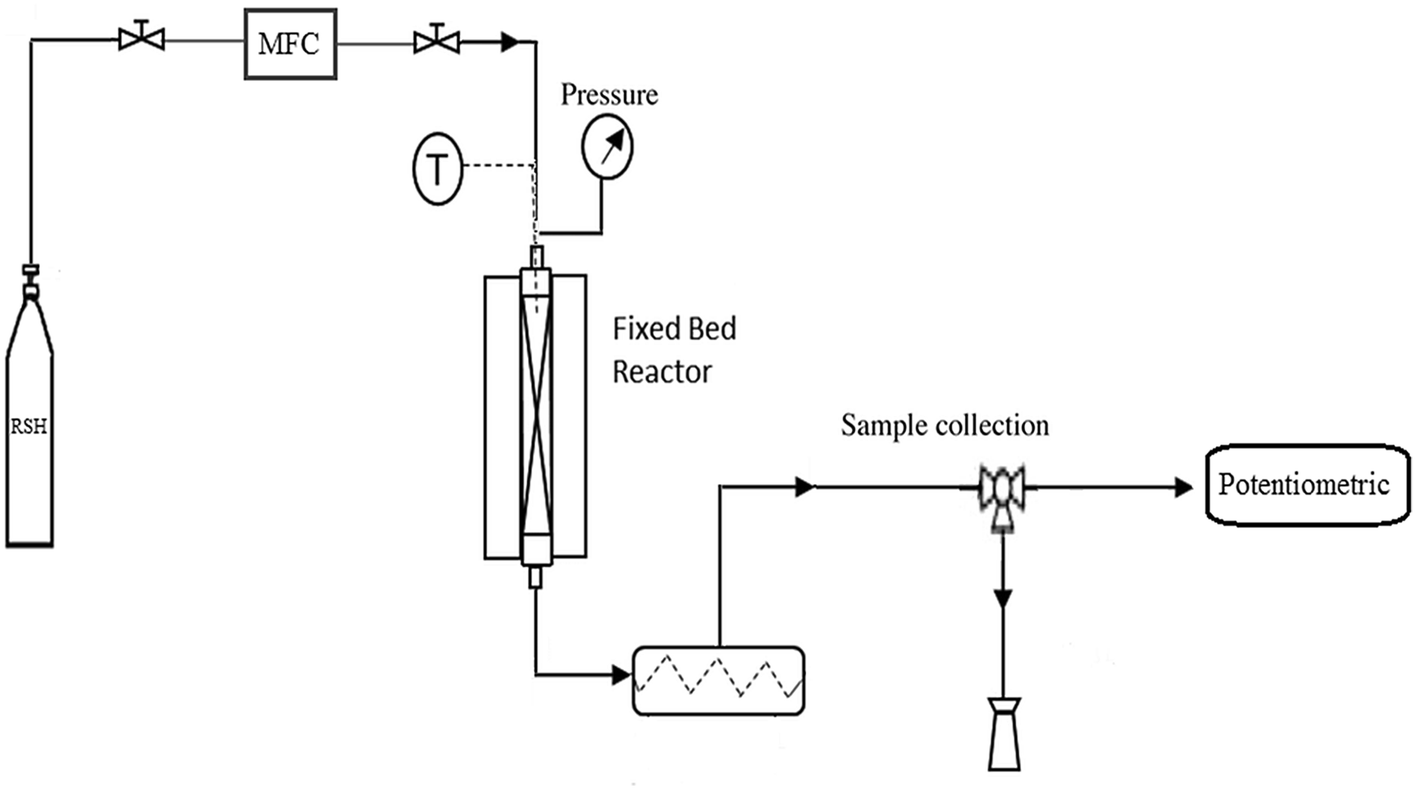
The fixed-bed reactor system for conversion of mercaptan is shown in Fig.
3
. The generation gases were kept in pressurized tanks. The nanocatalyst was put in a vertical quartz reactor, made up of a stainless steel-314 tube (12.5 mm i.d. and 450 mm length), which was set in the center of the tubular furnace and equipped with a temperature control device. In this experiment, feed includes a hydrocarbon mixture (98.63wt%) of n-butane, ethyl mercaptan (0.010 wt%, 10,000 ppm) and H
2
O (0.0037 wt%) which was carried to the top point in the reactor. A mass flow controller (MFC) was used to adjust gas flow that was connected to a (JUMO dTRON 304) electronic control unit. The ambient temperature of the nanocatalyst was increased up to the reaction temperature. In this experiment, various operating conditions such as reaction temperature and Gas Hour Space Velocity (GHSV, h
−1
) were introduced to collect the experimental data. In addition, GHSV was determined according to the volume (ml) and velocity (ml/min) of the catalyst and inlet gas, respectively. The outlet gas was passed through a KOH solution (20%) at different times. Concentration of product mercaptan was determined at 30-min intervals using EM potentiometer (AT-500) and UOP 163 method [
15
,
16
].
Diagram of the experimental setup for mercaptan removalFig. 3
The experiments were conducted in temperature range of 50–100 °C, GHSV of (1000–3000 h
−1
) to remove mercaptan: maximum rate of mercaptan removal from gas stream was 150 ppm. Figure
4
shows the results of using this nanocatalyst for mercaptan removal.
Mercaptan conversion under GO support and GO-FeTCPP nanocatalystFig. 4
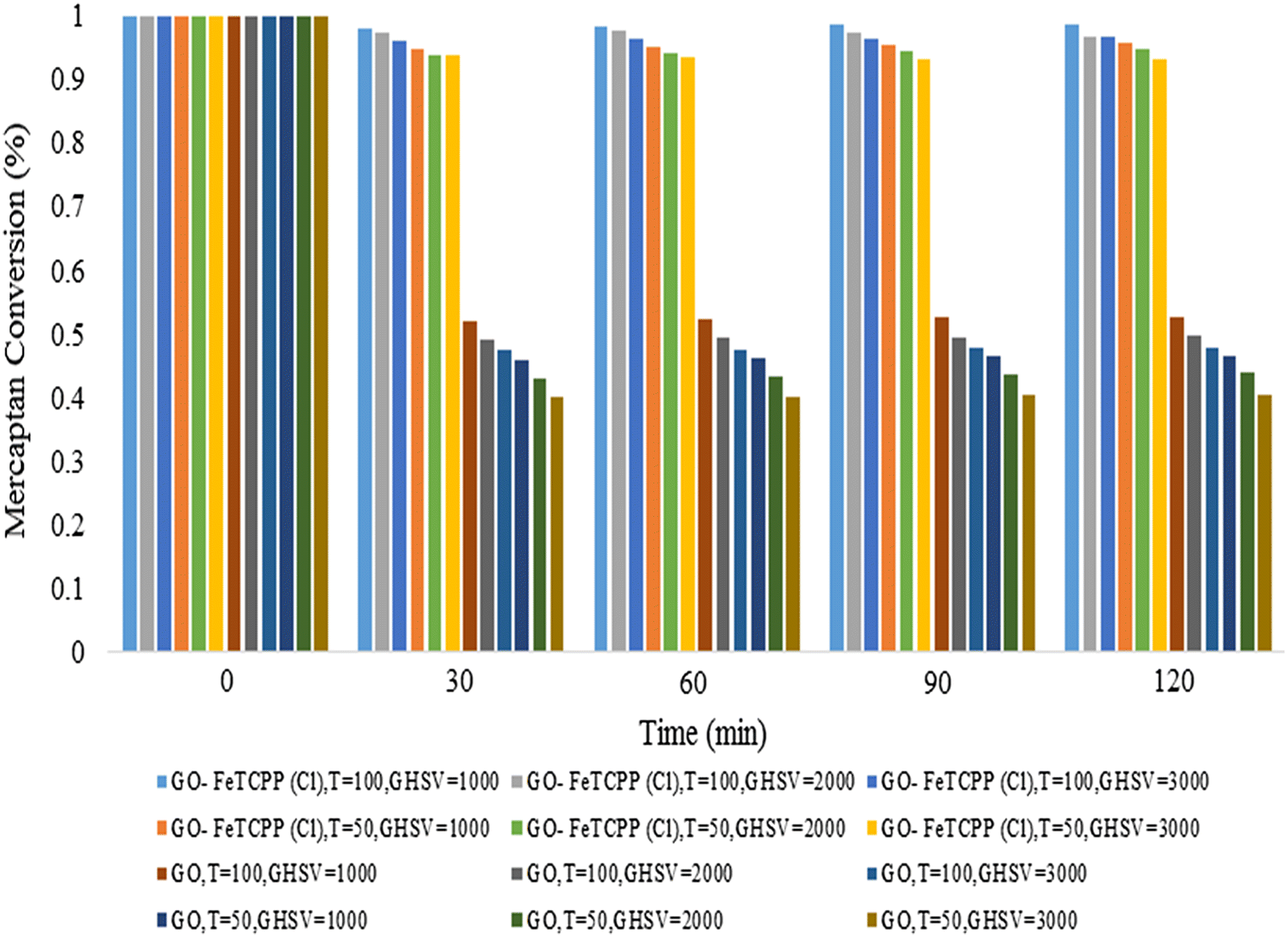
The dwindling mercaptan production rate in products of GO-FeTCPP (Cl) nanocatalyst was found to be much greater than in GO support. The higher activity of the GO confirmed the hypothesis that nanocatalyst for mercaptan removal reaction can be explained by strong bonds between acidic groups of FeTCPP (Cl) and the carboxylic groups of GO. Nanostructures such as GO can turn pore volume into potential support for porphyrin structure. Moreover, a GO support leads to emergence of active sites on the catalyst which in turn lead to greater surface area between the gas flow on one hand and the nanocatalyst on the other. As a result, mercaptan conversion becomes greater in the outlet stream [
15
,
16
]. Figure
5
a shows the effect of temperature on the removal of mercaptan in the range of 50–100 °C and a fixed amount of GHSV (1000 h
−1
). Obviously, higher temperatures contribute to reaction rate and the nanocatalyst activity, a fact that explains the increased mercaptan conversion.
Results from the effect of temperature on mercaptan removal at GHSV: 1000 h
−1
(
a
) and effect of GHSV on mercaptan removal at T: 100 °C (
b
)Fig. 5
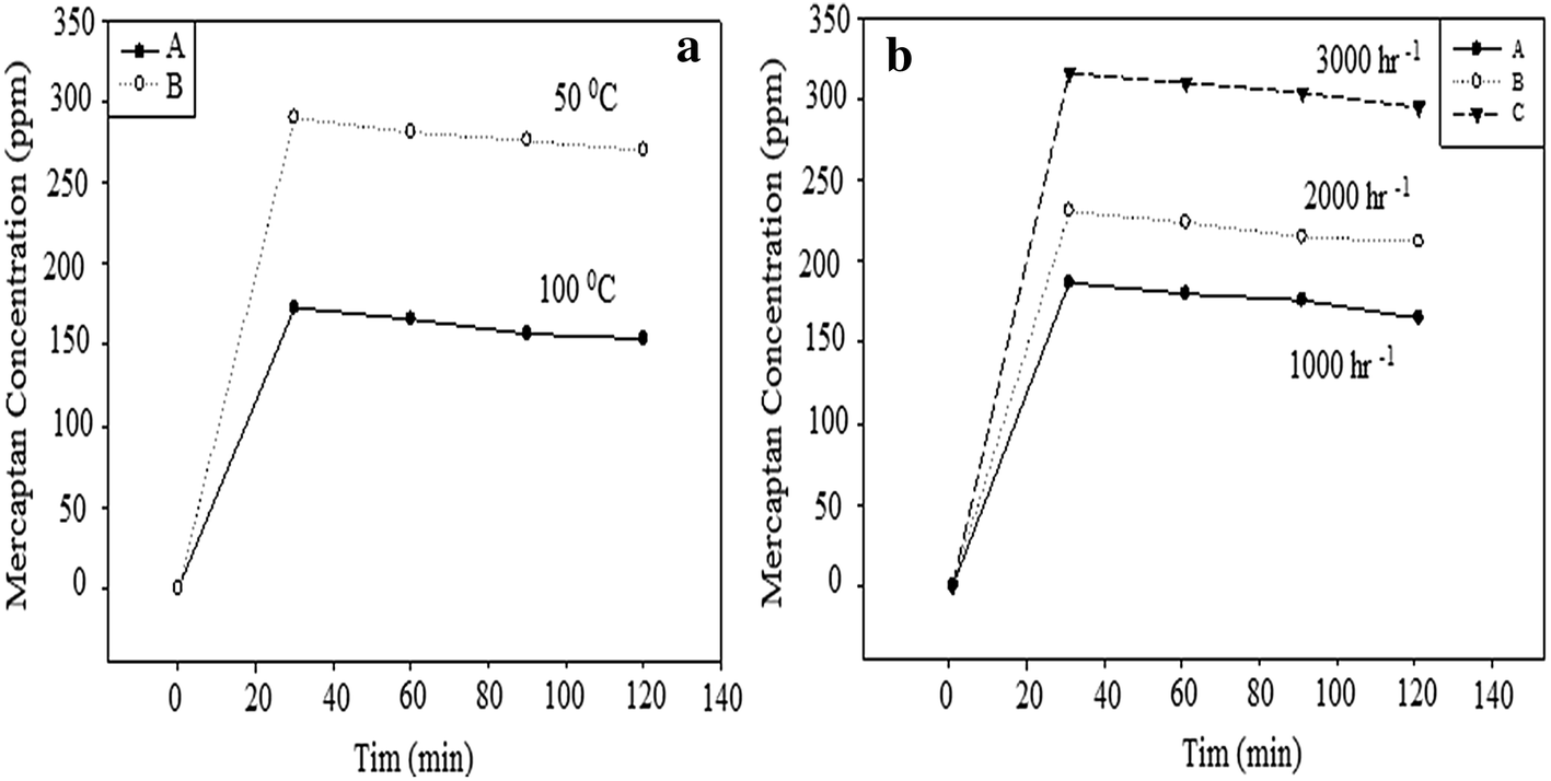
Figure 5 b shows the effect of GHSV on removal of mercaptan in 1000–3000 h −1 range at 100 °C. As can be seen, by increasing GHSV, the speed of the reactant rises, while the residence time decreases; thus, lower adsorption happens on the catalyst surface.
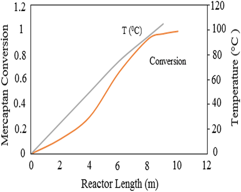
Figure
6
shows the conversion rate of mercaptan along the reactor length. The rate of conversion rose from the inlet of the reactor simultaneous with the increase of temperature.
Effect of reactor length on the rate of mercaptan conversion and temperature reactorFig. 6
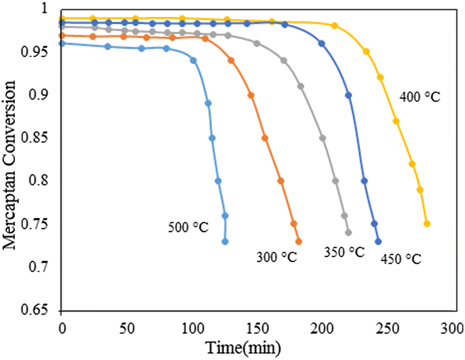
As regeneration temperature is an essential factor for catalyst performance, regeneration of the FeTCPP (Cl)-GO nanocatalyst was examined and the results illustrated in Fig.
7
. The regeneration of the nanocatalyst was performed under nitrogen condition at the different temperatures. When nanocatalyst was regenerated at temperature of 400 °C, the highest rate of mercaptan conversion was achieved. In the lower temperature, there is no impact on the oxidation of the nanocatalyst due to the fact that the ability of regeneration at low temperatures is reduced. In addition, physical and chemical properties of nanocatalyst were changed at high temperature, resulting in the complex products which may be decomposed under this condition. Further study of the regeneration process should be performed in the future.
Effect of regeneration temperature on the removal of mercaptan under FeTCPP (Cl)-GO nanocatalystFig. 7
The most valid mechanism for the mercaptan removal process is listed below: the general reaction:
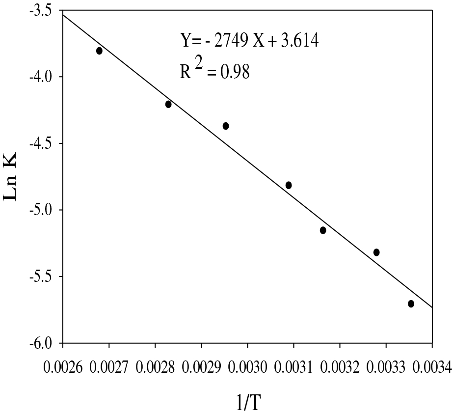
The demercaptanization reaction is a first-order reaction and the first-order reaction was determined by curve fitting method for mercaptan removal at the presence of FeTCPP(Cl)-GO nanocatalyst and as shown in Fig.
8
, the Arrhenius plot was obtained with the value of
R
2
(0.98). As can be seen, increasing the temperature strengthens the rate of mercaptan removal reaction. The reaction rate equation for FeTCPP (Cl)-GO nanocatalyst can be written as:
Arrhenius plot for mercaptan conversionFig. 8
In this investigation, a heterogeneous nanocatalyst was developed for removal of mercaptan in a fixed bed reactor. For this purpose, FeTCPP (Cl)-GO nanocatalyst was prepared by synthesis of FeTCPP (Cl) complex within GO as a support. Kinetic parameters related to catalytic reaction for FeTCPP (Cl)-GO nanocatalysts were obtained. The Raman spectrum of nanocatalyst displayed an enhancement of the ratio ( I D / I G ) as a result of successful attachment of FeTCPP (Cl) complex onto the GO surface. In addition, the FT–IR spectra for FeTCPP (Cl) indicated a new peak at 1570 cm −1 while the peak of the C–O stretching vibration moves to 1105 cm −1 . The GO-FeTCPP (Cl) nanocatalyst showed a (001) peak at 2 θ = 9°, a figure smaller than that of GO. According to SEM images, the average size of nanoparticles was approximately 20–50 nm and the isotherm of GO-FeTCPP (Cl) nanocatalyst was classified as Type I. Regarding regeneration process, catalyst can be recovered and the highest rate of mercaptan conversion was obtained at 400 °C. The results of the study show temperature as a major factor in controlling the conversion. On the other hand, the conversion rate of mercaptan under nanocatalyst increased by the increase of temperature value and the decrease of GHSV. Finally, the maximum conversion of reaction in the best condition was obtained at GHSV of 1000 h −1 , T of 100 °C, and conversion of 96%.
Springer Nature remains neutral with regard to jurisdictional claims in published maps and institutional affiliations.