Architecture and Building Systems, Institute of Technology in Architecture (ITA), ETH Zurich, Zurich, 8093, CH
ZJA, Zwarts & Jansma Architects, Amsterdam, NL-1086 XK, NL
Abstract
Most photovoltaic modules are planar and as a result, research on panel layout for photovoltaic systems typically uses planar panels. However, the increased availability of thin-film photovoltaic modules opens up possibilities for the application of flexible solar panels on irregularly curved surfaces, including the integration of photovoltaic panels on building roofs with double curvature. In order to efficiently arrange photovoltaic panels on such surfaces, geometric CAD tools as well as radiation analysis tools are needed. This paper introduces a method to generate geometry for flexible photovoltaic modules on curved surfaces, as well as a method to arrange multiple of such modules on a surface. By automating the generation of possible photovoltaic panel arrangements and linking the geometric tools to solar analysis software, large numbers of design options can be analysed in a relatively short time. This combination of geometry generation and solar analysis provides data that is important for electrical design of photovoltaic systems. The merits of the methods we introduce are illustrated with a case study, for which hundreds of design configurations have been explored in an automated manner. Based on analysis of the numeric data generated for each of the configurations, the effects of panel dimensions and orientation on solar insolation potential and panel curvature have been established. The quantitative and qualitative conclusions resulting from this analysis have informed the design of the photovoltaic system in the case study project.
Introduction
Strong cost reductions and increasingly stringent government regulations combined with support schemes for renewable energy in several countries are leading to a rapid deployment of photovoltaic (PV) systems. Many studies exist on the topic of placement and orientation of PV panels on roofs, facades or the ground, but solely taking into account flat modules on planar surfaces [
1
–
5
]. With the increased availability of flexible thin-film PV panels in recent years, the application of PV panels on curved surfaces becomes feasible, thus broadening the application potential of photovoltaic modules. Curvature poses some major challenges related to structural integration, PV module operation and electrical system design [
6
,
7
]. However, so far no methodology for modeling of flexible PV modules on curved surfaces exists. In this paper, we introduce design and analysis methods for the application of flexible PV panels on irregularly curved surfaces.
The design of buildings that are optimised for structural efficiency [
8
] or tailored for digitally informed fabrication [
9
,
10
] often results in complex geometry [
11
–
13
], which may include roofs and facades featuring double curvature. Due to their rigidity and shape, most PV panels are difficult to integrate in surfaces with double curvature. However, thin-film photovoltaic modules can be applied to thin sheet metal or flexible polymer substrates, offering more geometric flexibility. Combined with the high efficiency and low weight of thin-film PV technologies such as CIGS (copper indium gallium selenide), this offers new application possibilities of PV modules for building integrated photovoltaics (BIPV) as well as portable PV applications [
14
]. With this technique, thin-film photovoltaic modules could potentially be directly integrated in the building envelope. As this would remove the need for the substructures that are typically used for PV installations, such a system could be light-weight and cost-effective.
Flexible sheet metal panels can be applied to surfaces with single curvature easily and have historically been used for roofing [
15
]. However, when applying bendable panels to surfaces with double curvature, methods to predict the geometric behaviour of such panels are needed. When these geometric methods are linked to solar analysis, the amount of solar insolation can be predicted at any desired spatial resolution. Such solar insolation data is important for the electrical design of PV systems: taking shading conditions into account reduces electrical mismatch and thus results in significantly higher electricity generation [
16
,
17
].
Approximation of double-curved surfaces by triangulation was already used in the pre-digital era in the context of sheet metal working [
18
], but this process is labour intensive and thus only suitable for lofted surfaces with few control curves, as shown in Fig.
1
(left). The geometric methods presented in [
19
] and [
20
] approximate a surface by triangulation and then unfold the triangles into a flat surface with a shape that is not known in advance. In our geometric methods, we take the rectangular shape of unbent panels as a starting point and triangulate them in order to approximate the original surface. Methods presented in [
21
] also create strip-like surfaces, but allow deviations from exact rectangular shapes that are not permissible in the photovoltaic modules we employ.
Fig. 1
Left
: triangulation method described by Kidder [
18
].
Right
: our method
In a pilot project, the geometric methods we developed have been used to generate hundreds of configurations of flexible PV panels on an irregularly curved roof. After running solar insolation simulations for each configuration, the influence of panel dimensions and panel orientation on solar insolation were analysed.
This paper starts by introducing methods to approximate double-curved geometry using developable strips. After assessing the validity of these methods, we then discuss how the resulting geometry can be analysed on a number of metrics: total surface area, occurrence of bending, surface approximation accuracy and solar insolation. We then show the application of these methods to a case study building and discuss the results, focusing on the influence of various design parameters on the total solar insolation.
Methods
In this section, we introduce methods to generate strips of bendable photovoltaic panels by approximating a double-curved surface using two different triangulation approaches (2.1–2.3), to efficiently arrange multiple of these strips on a larger surface (2.4) and to analyse the resulting geometry with regard to various geometric metrics (2.5) as well as solar insolation (2.6).
Panel generation method A: congruent triangles
Our aim is to generate an approximation of a flexible panel that is bent over a double-curved surface, following the surface as closely as possible while remaining developable and resulting in an exactly rectangular shape when unrolled.
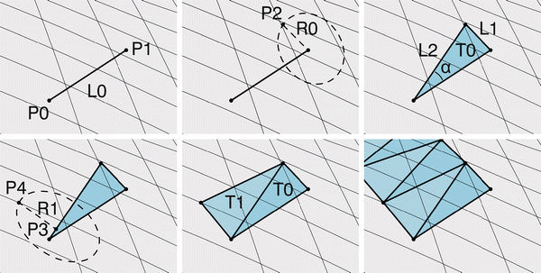
As triangulated strips are perfectly developable, we decided to approximate the final shape of the photovoltaic panels by a series of triangles, of which all corner points lie exactly on the roof surface. The method to generate this geometry is shown in Fig.
2
.
Fig. 2
Surface approximation using congruent triangles (method A)
The following sequence of steps results in a regularly triangulated surface that approximates the base surface:
Create two points (P0, P1) on the base surface, such that the distance between them is the desired panel width (w) and the direction is perpendicular to the desired panel direction. Connect the points with a line (L0).
Create a circle with radius R0 around point P1, using a plane perpendicular to line L0. Create a point (P2) at the intersection of this circle with the base surface.
Create two lines (L1, L2) connecting point P2 to points P0 and P1, thus creating triangle T0 with angle α at P0.
Create a point (P3) on L2 at distance
w·cosα
from P2, then create a circle perpendicular to L2 around P3 using radius
w·sinα
. Intersect this circle with the base surface, creating point P4.
Connect P4 with two lines to points P0 and P2, creating triangle T1. Note that triangles T0 and T1 are congruent.
Repeat steps 2–5 as many times as necessary.
Panel generation method B: adaptive triangles
Although the method described in “
Panel generation method A: congruent triangle shapes
” does work for strips with changing curvature direction, it deals better with curvature along the length of the strip than with curvature perpendicular to that direction. In order to minimise the surface deviation of the triangulated strips, we tested a second triangulation method that deals better with situations where the main surface curvature direction is close to perpendicular to the panel’s length direction. This method is shown in Fig.
3
.
Fig. 3
Surface approximation using adaptive triangles (method B)
The following sequence of steps results in an irregularly triangulated surface that approximates the base surface and exactly unfolds into a rectangle:
Create two points (P0, P1) on the base surface, such that the distance between them is the desired panel width (
w
) and the direction is perpendicular to the desired panel direction. Connect the points with a line.
Create a series of lines starting at P0 and ending at points on the surface with distance
n·d
from P1 and
n·d2+w2
from P0, where
n
is the number of lines and
d
is a distance that can be chosen at will. Create a second series of lines starting at point P1. Select the line that has the smallest distance between its midpoint and the base surface and call the endpoint of this line P2.
Draw a triangle using points P0, P1 and P2.
Continue creating triangles by repeating steps 2 and 3. Note that in some cases, more than two diagonal lines meet in one point, such as point 5 in Fig.
3
.
The end of the strip is a special case: if an exact strip length is desired, the value for distance
d
in step 2 should be set to the remaining edge length divided by an integer (which may be chosen at will). Once one of the corner points of the strip has been reached, potential end points can be created on the panel’s short edge.
Assessment of panel triangulation methods
In order to assess the extent to which triangulation methods A and B reflect actual bending behaviour of sheet metal, we created a physical model. Additionally, we studied the effect of changing the diagonal direction in method A, and we compared the geometric differences between methods A and B (Fig.
4
).
Fig. 4
Comparison of triangulation methods A (
dashed
,
dotted
) and B (
solidline
)
In a test of 46 triangulated strip segments generated with method A, the median lateral deviation between strips using different diagonal directions turned out to be 0.14 % of the strip length. In the most extreme case, the lateral deviation was 2.1 %.
Comparing method A with method B, the median lateral deviation on our test geometry is 0.20 %. The most extreme deviation occurring is 3.7 %.
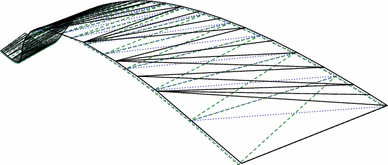
Two scale models were created to test the sheet metal strip behaviour: one supported by elements perpendicular to the strip direction (generated with method A), and one supported by elements oriented roughly along the main curvature direction (using a subset of edges generated using method B).
Once mounted, the metal strip follows the predicted trajectory accurately in both models, as shown in Fig.
5
. Deviations turned out to be smaller than the thickness of the supporting material, which suggests that the digital approximation is a good representation of the bending behaviour of sheet metal strips that are locally fixed along their edges.
Fig. 5
Scale model showing metal strips bent over edges created with methods A (
bottom
) and B (
top
)
An observation relevant to the fixation method of the panels is that perpendicular supports visibly deform the metal surface in areas of concave curvature, except when the main curvature direction is aligned with the strip. To avoid this visible deformation, the supports for the panels can be aligned to the local curvature direction of the strips.
Geometric method for strip arrangement
The methods shown above can be used to generate single strips, but in order to cover a larger area, a method to arrange multiple strips is needed. To maximise solar insolation, we are looking for a solution that fits as many panels as possible. As an additional architectural constraint, we choose to only look at solutions where multiple panels are arranged in long strips.
On a surface with double curvature, strips that are parallel to each other at one position will diverge or overlap elsewhere. We aim to avoid overlapping and to keep strips roughly parallel to each other, so that the unused area between panels is minimised. However, in order to facilitate the installation process, a certain minimum distance between the panels is defined.
At any point along the length of a strip, a parallel strip can be created by taking the direction of the closest point in the existing strip as the start direction, as illustrated in Fig.
6
. In order to pick the best panel out of the generated options, we use a formula favouring long neighbour strips and small differences between the gap sizes near the ends of the panels:
Fig. 6
A series of potential neighbour panels (
above
) for an existing panel (
below
)
Suitability=Lc-mind1,d2/maxd1,d2
In this equation,
L
is the length of the new strip and
d
1 and
d
2 are distances between two strips at both ends (see Fig.
7
). Constant
c
should be larger than one, as otherwise very short strips would be favoured over significantly longer, but slightly less parallel strips. For this analysis, we set the value of
c
to 1.1.
Fig. 7
A potential neighbour panel. The length of the new panel and the distances
d
1 and
d
2 are used to determine the new panel’s suitability
By applying this method iteratively until the roof edge has been reached, large irregular surfaces can be covered with strip geometry, as illustrated in Fig.
8
.
Fig. 8
A series of strips approximating a hyperboloid surface
Calculation of bending and of surface approximation accuracy
The amount of module bending and the accuracy of surface approximation are important metrics as they strongly influence buildability, detail design and visual appearance.
We calculate approximate panel bending radii at every point along the strip edges by determining the angles between sets of three consecutive edge points, which in the examples in Fig.
9
are 15 cm apart. Radii that are close to or shorter than a user defined minimum radius are marked in the graphical output (see Fig.
9
, left).
Fig. 9
Left
: graphical display of bending radii.
Right
: graphical display of surface deviation at the centre curve of the strips
In order to get an estimate of the geometric deviations between the original surface and the generated strips, we measure the distance between various points of the strip geometry and the nearest points on the original surface. As all points on both sides of the generated strips lie exactly on the base surface, the points with the largest surface deviation typically lie very close to the centre line of the strips. As with the bending radii, this surface approximation accuracy is exported both graphically (see Fig.
9
, right) and numerically.
Calculation of solar insolation
The solar insolation of all generated panel configurations has been analysed using the EnergyPlus building energy simulation software [
22
], which we accessed through the Ladybug [
23
] plugin for Grasshopper [
24
], which is a parametric modelling and programming environment for the 3d modelling program Rhinoceros [
25
]. Using EnergyPlus weather files with hourly resolution, Ladybug calculates irradiance on the modules with the cumulative sky approach [
26
,
27
]. For the analysis presented in this work, the spatial resolution of the strip-like panels is ten triangular faces per stretching meter.
As weather data source, we used IWEC weather data for Geneva [
28
], covering one calendar year at one hour intervals. Using custom C# scripts, both graphical and numerical output were generated. Sun paths generated with the DIVA [
29
] plugin for Grasshopper were then used to visually study shadow occurrence on the roof, using the physically based render engine LuxRender [
30
].
The curved geometry leads to varying irradiance on the modules, which in turn induces electrical mismatch between cells and modules [
31
,
32
]. Though not investigated in this paper, coupling module irradiance with an electrical model can be used to predict PV module power-voltage characteristics. This is important for efficient system design such as the development of advanced maximum power point tracking methods [
31
,
32
] or distributed power electronics [
33
].
Results
The methods presented above have been applied in the context of the design of the NEST Hilo building at EMPA Dübendorf, which is a test bed for novel building technology [
34
]. The building features a double-curved roof, the shape of which is defined by structural considerations and a scaffolding process using textile formwork [
35
]. Photovoltaic cells mounted on thin, bendable metal plates will be placed on top of this roof, arranged in long parallel strips as shown in Fig.
10
. Our first aim is to assess the solar insolation of various shell shapes and thus provide design feedback on the energy production potential. Our second aim is to define panel dimensions and a panel arrangement on the final roof shell in a way that results in a high PV solar insolation, while in parallel fulfilling architectural and technical requirements.
Fig. 10
Model of a series of bent photovoltaic panels placed on the Hilo building roof
Comparative analysis of various roof shell shapes
When comparing a series of seventeen roof shapes, the solar insolation per square meter varied by about 8 % between the best and the worst roof shape. The highest insolation was achieved with shapes that are mostly flat and concentrate any necessary steep geometry in small areas of the roof surface. Roof shapes with larger, less steep valley areas did less well; the lower solar insolation is the result of more self-shading. This is illustrated in Fig.
11
.
Fig. 11
Two of the seventeen alternative roof shapes (
left
) and graphic display of solar insolation over a year on these shells (
right
). Due to self-shading and a less favourable orientation, roof B has significantly lower solar insolation than roof A
Analysis of design parameters, as applied to case study roof
Using the methods described in the methods section, we assessed the impact of relevant design parameters (panel dimensions and strip orientation) on solar insolation, panel bending and surface deviation of strips. This was done by evaluating the relevant metrics for every combination of the following parameters:
Panel width
0.30, 0.45, 0.60, 0.75 and 0.90 m
Panel length
1.2, 1.6, 2.0, 2.4 and 2.8 m
Strip orientation
13 angles, at 15° intervals
In total, this resulted in data for 325 design alternatives. A detailed analysis of this data applied to one specific roof shape is presented in the following sections.
Surface area as a function of panel dimensions
The dimensions of the panels have a clear influence on the solar insolation:
The available length for a strip is rarely an exact multiple of the panel length, so part of the available area will not be used. The size of the unused area depends on the angle between the panel and the edge, and on the panel length. On average, more than half a panel length of potential space is lost on each strip. Using shorter panels helps reduce these losses.
The effect of panel width on active surface area is clear: the use of wider panels results in a smaller loss of potential roof area, as there are fewer gaps between panels.
In practice, photovoltaic panels often have an inactive edge area. The losses caused by these edges are relatively strong for narrow and/or short panels. Still, for common panel sizes, short, wide panels result in the largest active PV surface in our case study, as can be seen in Fig.
12
.
Fig. 12
Achievable active module surface as a function of panel length and width, assuming an inactive edge area of 1.5 cm wide
Active panel surface area as a function of panel strip orientation
Certain strip orientations result in a denser arrangement of strips and thus in a larger active surface area than other orientations, as can be seen in Fig.
13
. Long strips typically result in more variation in the width of gaps between panels, which may be due to the longer distances over which the gaps can accumulate. The strength of this effect depends on the base geometry.
Fig. 13
Strip arrangements using various starting angles. From left to right: 90°, −30° and 15°
In our case study, the best results were achieved when orienting strips mostly perpendicularly to the longest roof edges (see Fig.
13
, right). As Fig.
14
shows, the difference between various orientations is significant: almost 14 %.
Fig. 14
Average surface area as a function of strip orientation
Strip bending as a function of strip orientation
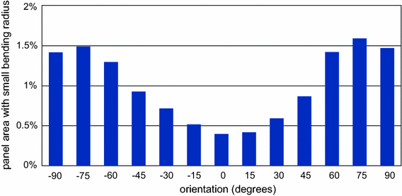
On the topic of bending, considering the possible arrangements of strips on a cylinder shows that the strip orientation can have a large impact on the amount of bending within the strips as it can range from 0 (following the direction of the cylinder) to totally curved (following the circumference of the cylinder). The same thought experiment suggests that the width of the strips does not affect the amount of bending in the length direction of the strips.
Analysis of the amount of bending occurring for various strip widths and orientations on our roof shape confirms the expected behaviour: the strip width does not significantly affect the amount of panel bending, but as shown in Fig.
15
, the orientation of the panels does.
Fig. 15
Occurrence of strong bending for various strip angles: percentage of panel area that features bending at a small radius
Effect of panel dimensions on surface approximation accuracy
Strip width logically affects the accuracy with which the original surface can be approached. Using strips of 0.30 m wide, the distance between the original surface and the generated strips is less than 5 mm for most of the area and never larger than 20 mm. However, as can be seen in Fig.
16
, the surface approximation is much less accurate when using wider panels. This has aesthetic consequences but may also affect the panel mounting system.
Fig. 16
Surface deviation for strips of various widths
Solar insolation
For the roof geometry we studied, the starting direction of the strips on the roof has only a small effect on the average orientation of the strips: the average normal direction between various configurations varies less than three degrees. As can be seen in Fig.
17
, the starting direction of the strips also has very little influence on the average irradiance on the roof strips. Therefore, the total annual insolation is mostly dependent on the total surface area of the PV strips and the results discussed in “
Surface area as a function of panel dimensions
” and “
Active panel surface area as a function of panel strip orientation
” directly apply to solar insolation as well.
Fig. 17
Influence of strip starting direction on average yearly irradiance
Conclusions
In this paper, we introduce methods to design and analyse photovoltaic systems using flexible panels, which facilitates the application of photovoltaic systems on curved surfaces where other photovoltaic systems would not be suitable. Thanks to the systematic generation of flexible panel geometry, we were able to identify the influence of various geometric parameters (including panel dimensions and panel arrangement) on the potential surface area of photovoltaic panels on a double-curved roof, as well as on the expected solar irradiation on such panels.
We have introduced geometric methods to approximate double-curved geometry using triangulated strips, as well as methods to organise such strips efficiently on a surface. By combining these methods with solar insolation analysis software, we analysed the solar insolation potential of various roof shell geometries in a case study project. We also studied the impact of various geometric parameters on solar insolation, module curvature and the size of the gaps between the flexible panels and the roof surface.
For the roof geometry we studied, the solar insolation is almost perfectly linearly dependent on the panel surface area. Short and wide panels that are oriented mostly perpendicularly to the longest edges of the roof resulted in the largest effective PV area and in the highest solar insolation. On the other hand, narrow panels result in less geometric deviation between the flexible panels and the roof surface.
The methods we introduced proved to work reliably and efficiently in our case study, despite the geometric complexity of the roof. This suggests that the methods work for a wide range of shapes. Because the strip geometry generation and irradiance analysis are automated and take little time to calculate, the system described in this paper could potentially be linked to other computational design tools. Data generated using the presented method could be used to inform the electrical design of photovoltaic systems.
Acknowledgments
This research has been financially supported by Swiss Commission for Technology and Innovation (CTI) within the Swiss Competence Center for Energy Research (SCCER) Future Energy Efficient Buildings & Districts (FEEB&D, CTI.2014.0119) and by the Building Technologies Accelerator program of Climate-KIC. The base geometry for the case study roof has been kindly provided by Diederik Veenendaal at the Block Research Group, ETH Zurich.
References
Díaz-Dorado et al. (2011) Optimal distribution for photovoltaic solar trackers to minimize power losses caused by shadows 36(6) (pp. 1826-1835) 10.1016/j.renene.2010.12.002
Ng et al. (2014) Assessment of solar radiation on diversely oriented surfaces and optimum tilts for solar absorbers in Malaysian tropical latitude 5(1) (pp. 1-13) 10.1007/s40095-014-0075-7
Gordona and Wengera (1991) Central-station solar photovoltaic systems: field layout, tracker, and array geometry sensitivity studies 46(4) (pp. 211-217) 10.1016/0038-092X(91)90065-5
Choo and Janssen (2014) Evolutionary optimisation of semitransparent building integrated photovoltaic facades 12(1) (pp. 81-100) 10.1260/1478-0771.12.1.81
Sun et al. (2012) Optimum design of shading-type building-integrated photovoltaic claddings with different surface azimuth angles (pp. 233-240) 10.1016/j.apenergy.2011.01.062
Unknown ()
Sharma et al. (2012) A novel approach for maximum power tracking from curved thin-film solar photovoltaic arrays under changing environmental conditions 50(6) (pp. 4142-4151) 10.1109/TIA.2014.2322136
Williams et al. (2011) A case study of a collaborative digital workflow in the design and production of formwork for ‘non-standard’ concrete structures 9(3) (pp. 223-240) 10.1260/1478-0771.9.3.223
Lin (2014) Flexible photovoltaic technologies 2(7) (pp. 1233-1247) 10.1039/c3tc32197e
Yalden (1920) The design and construction of a small observatory (pp. 449-458)
Hofer et al. (2016) Parametric analysis and systems design of dynamic photovoltaic shading modules 4(2) (pp. 134-152) 10.1002/ese3.115
Dolara et al. (2013) Experimental investigation of partial shading scenarios on PV (photovoltaic) modules (pp. 466-475) 10.1016/j.energy.2013.04.009
Kidder (1917) The Sheet Metal Publication Company
Frey (2002) Boundary triangulations approximating developable surfaces that interpolate a closed space curve (pp. 285-302) 10.1142/S0129054102001096
Tang and Wang (2005) Modeling developable folds on a strip 5(1) (pp. 35-47) 10.1115/1.1804206
Wallner et al. (2010) Tiling freeform shapes with straight panels: algorithmic methods (pp. 73-86) Springer 10.1007/978-3-7091-0309-8_5
Crawley et al. (2000) EnergyPlus: energy Simulation Program 42(4) (pp. 49-56)
Unknown ()
Unknown ()
Unknown ()
Unknown ()
Unknown ()
Unknown ()
Unknown ()
Unknown ()
Konstantopoulos and Koutroulis (2014) Global maximum power point tracking of flexible photovoltaic modules 29(6) (pp. 2817-2828) 10.1109/TPEL.2013.2275947
Sharma et al. (2014) A novel approach for maximum power tracking from curved thin-film solar photovoltaic arrays under changing environmental conditions 50(6) (pp. 4142-4151) 10.1109/TIA.2014.2322136
Unknown ()
Unknown ()
Veenendaal and Block (2014) Design process for a prototype concrete shells using a hybrid cable-net and fabric formwork (pp. 39-50) 10.1016/j.engstruct.2014.05.036