Department of Mechanical Engineering, Technical University of Denmark, Kgs. Lyngby, 2800, DK
Danish Technological Institute, Århus, 8000, DK
Abstract
Spray-drying facilities are among the most energy intensive industrial processes. Using a heat pump to recover waste heat and replace gas combustion has the potential to attain both economic and emissions savings. In the case examined a drying gas of ambient air is heated to 200 °C yielding a heat load of 6.1 MW. The exhaust air from the drying process is 80 °C. The implementation of an ammonia–water hybrid absorption–compression heat pump to partly cover the heat load is investigated. A thermodynamic analysis is applied to determine optimal circulation ratios for a number of ammonia mass fractions and heat pump loads. An exergoeconomic optimization is applied to minimize the lifetime cost of the system. Technological limitations are imposed to constrain the solution to commercial components. The best possible implementation is identified in terms of heat load, ammonia mass fraction and circulation ratio. The best possible implementation is a 895 kW heat pump with an ammonia mass fraction of 0.82 and a circulation ratio of 0.43. This results in economic savings with a present value of 146,000 € and a yearly CO
2
emissions reduction of 227 ton.
Introduction
Spray-drying facilities are among the most energy intensive industrial processes. They are applied in the production of dry solids from a liquid feedstock. This is typically needed in the chemical, pharmaceutical or food industry. Typical products of spray-drying processes are powdered milk, detergents and dyes. A survey from 2005 [
1
] showed that the yearly energy consumption for drying operation in the United Kingdom was 348.6 PJ, corresponding to 17.7 % of industrial energy consumption. Spray-drying processes are typically fuelled by fossil fuel combustion, most commonly natural gas [
1
]. Therefore, spray-drying facilities are not only accountable for a large energy consumption but also for a large quantity of green house gas emissions. Improving the energy efficiency of spray-drying facilities is thus important to reach the goals for a sustainable development of the industrial sector.
Given the recent and projected increase in renewable electricity generation from sources such as wind and solar [
2
], moving energy consumption from gas combustion to an electrically driven heat pump could be an environmental benefit.
The implementation of heat pumps in spray-drying facilities is typically restricted by the high temperature of the exhaust air (80–100 °C), which is out of the working domain for most industrial vapour compression heat pumps [
3
,
4
]. The ammonia–water hybrid absorption–compression heat pump (HACHP), however, has several attributes making it applicable for high-temperature operation [
3
,
5
].
The HACHP is based on the Osenbrück cycle [
6
]. The first theoretical study of which was performed by Altenkirch [
7
], who described the advantage of the HACHP heat pump with the non-isothermal process of absorption–desorption compared to the isothermal process of condensation–evaporation. Thereby, the cycle approaches the Lorenz cycle [
8
], which can increase the heat pump efficiency by reducing the entropy generation driven by heat transfer over a finite temperature difference.
Heat pump-driven drying processes has been studied by Prasertsan et al. [
9
], Gungor et al. [
10
] and Chua et al. [
11
]. These investigations have been limited to low-temperature drying processes due to the constrained heat supply temperature of conventional vapour compression heat pumps. The maximum supply temperature of vapour compression heat pumps is bound by the maximum allowable pressure of the compressor technology and the corresponding saturation temperature of the refrigerant [
4
].
Using a zeotropic mixture as working fluid reduces the vapour pressure compared to the vapour pressure of the pure volatile component. Using the newly developed high pressure ammonia components (50 bar max. pressure) heat supply temperatures up to 150 °C can be achieved using the HACHP [
5
]. The limit for a pure ammonia system with these components is 90 °C [
4
]. The development of these high pressure components and their combination with the HACHP technology has thereby shifted the working domain of industrial heat pumps, making it applicable for processes like spray-drying. However, whether this shift allows economic and environmental savings in industry is still unanswered and should be estimated to evaluate whether heat pump development should be moved in this direction.
Ommen et al. [
12
] presented exergoeconomic optimization of the HACHP. This showed that the HACHP can be competitive with gas combustion and that the HACHP is the only applicable heat pump technology in the temperature range of the present study. Ommen et al. [
12
] tested ammonia mass fractions of 0.7 and 0.9 and found the total cost to increase with the reduction of ammonia mass fraction. This assumes constant heat transfer coefficients for the absorption and desorption. It is though well known that the heat transfer coefficient of a refrigerant mixture can be reduced due to either mass diffusion resistance of the volatile component or an unfavourable change in the mixture transport properties [
13
,
14
]. The heat transfer reduction is increased when the mixture composition is moved away from the pure components. This effect is thereby not accounted for in [
12
]. Satapathy [
15
] and Hultèn and Berntsson [
16
,
17
] also conclude that the ammonia mass fraction should be as high as possible, [
15
] concludes this based solely on exergy analysis while [
16
,
17
] conclude this based on an evaluation of both COP and investment.
This paper will investigate the economic and environmental implication of implementing a HACHP in a spray-drying facility. Using detailed heat transfer correlations the effect of changing ammonia mass fraction will be accounted for. The heat pump load, ammonia mass fraction and the circulation ratio in the HACHP will all be analysed and optimized within commercial component constraints. Combination of four ammonia concentrations and four heat pump loads will be investigated. This yields a total of 16 design conditions at which the HACHP design will be optimized.
To optimize the design, an exergoeconomic optimization [
18
,
19
] is applied in each of the 16 conditions. By optimizing the design of each of the these 16 conditions, the best possible design can be found and the effect of changing heat pump load and ammonia mass fraction can be evaluated without bias.
The objective of the present work is thus to evaluate if implementing a HACHP in a spray-drying facility is: technically feasible, using current commercial components and further, if such an installation will be economically viable as well as environmentally beneficial.
Methods
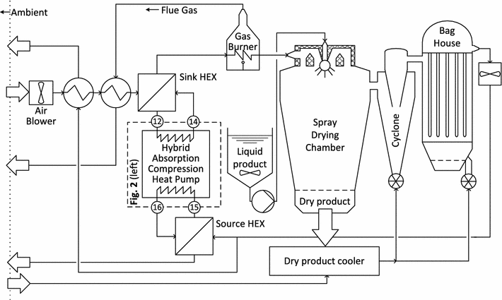
Spray-drying facility and heat pump implementation
A generic spray-drying facility, as seen in Fig.
1
, was studied. The HACHP was implemented to heat the drying air prior to the gas burner. A detailed overview of the HACHP unit (indicated by the dashed box) is shown in Fig.
2
(left), further the streams from Fig.
2
(left) that are present in Fig.
1
are indicated by the given stream numbers.
Fig. 1
Principle sketch of the investigated spray-drying facility
The ambient air is introduced to the system by an air blower at a rate of 100,000 m
3
/h. The air stream is first heated by a fraction of the exhaust air. Hereafter, it is heated by a flue gas heat recovery heat exchanger. The ambient air has a temperature of 20 °C and a humidity ratio of 0.006 kg/kg. At the outlet of the flue gas heat recovery heat exchanger, the drying air is 80 °C. From here, the drying air is heated by the HACHP, utilizing exhaust air as the heat source. The drying air is then heated to 200 °C by a natural gas burner.
Heating the air from 20 to 200 °C results in a total heat load of 6.1 MW. The larger the HACHP load, the more of the total heat load will be moved from the gas burner to the HACHP. As the exhaust temperature is uninfluenced by this: the temperature lift supplied by the HACHP increases with increasing load, thus decreasing the coefficient of performance (COP). It is, therefore, necessary to find a suitable HACHP load to ensure the viability of the investment.
When the air has reached the target temperature of 200 °C, it enters the spray-drying chamber and is mixed with the atomized stream of the liquid product. This causes the liquid in the product to evaporate. The dry product can then be extracted from the bottom of the chamber. The now more humid air is passed first through a cyclone and then a bag house filter to remove leftover product. Here, air heated by the dry product is introduced. The exhaust air exiting the bag house has a temperature of 80 °C, humidity ratio of 0.045 kg/kg and approximately twice the mass flow rate of the drying air. This means that the capacity rate of the exhaust is higher than that of the air being heated. Therefore, the exhaust stream can be split such that half can be used to heat the air directly and the rest can be used as the heat source in the HACHP. This, in combination with the use of a flue gas heat recovery heat exchanger ensures that there is an actual heat surplus at the exhaust air temperature. Consequently, the HACHP as implemented here will transfer heat across the pinch temperature [
18
]. The analysis and results presented in this paper are only valid for such systems. This is not always the case [
20
] and as a consequence of pinch analysis [
18
], the exhaust air is best utilized by heating the incoming air directly.
To reduce the risk of contamination, two secondary circuits are used to transfer the heat between the drying/exhaust air and the HACHP. The heat transfer fluid is water. On the sink side, this is pressurized to prevent evaporation. The secondary circuits will increase the HACHP temperature lift, thus reducing the COP, but is assumed to be a necessary safety measure.
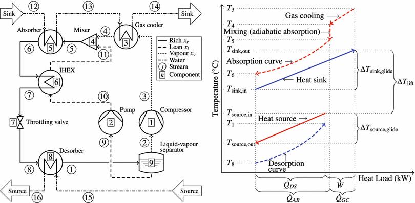
Modelling and analysis of the HACHP
The process diagram of the evaluated HACHP may be seen in Fig.
2
(left). The process is sketched in the temperature–heat load diagram shown in Fig.
2
(right). Here, it may be seen that the profiles of the absorption and desorption processes are non-linear. This has been described in detail by Itard and Machielsen [
21
]. In Fig.
2
, these are depicted as convex curves. Dependent on the ammonia mass fraction and circulation ratio, these profiles could also exhibit a concave curve or have a convex and a concave part. This is well described in Zheng et al. [
22
]. Therefore, when modelling the HACHP, it is not sufficient to ensure a positive temperature difference at the inlet and outlet of the absorber and desorber. To ensure a feasible profile, it is necessary to verify that there is a positive temperature difference over the entire heat transfer process.
Fig. 2
Left
principle sketch of the HACHP,
right
HACHP heat process sketched in a temperature heat load diagram
A numerical model of a HACHP has been developed in Engineering Equation Solver (EES) [
23
]. The thermodynamic properties of the ammonia–water mixture were calculated using equations of state developed by Ibrahim and Klein [
24
]. Transport properties were calculated using the correlation developed by El-Sayed [
25
], as suggested by Thorin [
26
]. Each component was modelled based on a steady state mass and energy balance. Further, the model ensured that the second law was fulfilled in all components.
The rich ammonia mass fraction,
xr
, and circulation ratio,
f
, were inputs to the model. The rich ammonia mass fraction is present in state 5–8 and 1. The circulation ratio was defined as the ratio between the mass flow rate of the rich solution,
m˙r
, and the lean solution,
m˙l
:
f=m˙lm˙r
Hence, the circulation ratio was directly linked to the vapour quality in state 1, exiting the desorber, such that:
q1=1-f
. From this it can be concluded that if,
f
= 0 then, the HACHP is essentially a vapour compression heat pump with a zeotropic working fluid.
Pressure and heat losses in the liquid/vapour separator were neglected, hence the temperature and pressure of stream 2 and 9 were the same as stream 1. It was assumed that the vapour and liquid exiting the separator were saturated,
q2
= 1 and
q9
= 0. The vapour and lean ammonia mass fraction,
xv
and
xl
, were then determined by equilibrium. The processes in the compressor and pump were modelled as adiabatic with given isentropic efficiencies,
ηis
. The transferred heat in the internal heat exchanger (IHEX) and gas-cooler was calculated based on given values of effectiveness,
ϵ
.
The mixing or adiabatic absorption process, found prior to the absorber, was modelled as an isobaric process by a mass and energy balance. Thus, state 5 was the equilibrium state attained when mixing stream 4 and 11. The state exiting the absorber was assumed to be saturated,
q6=0
. The forced adiabatic expansion in the throttling valve was assumed to be isenthalpic,
h7=h8
.
The high and low pressures,
pH
and
pL
, were determined to satisfy given values of pinch-point temperature difference,
ΔTpp
, in the absorber and desorber. As enthalpy and temperature are not proportional during the process of absorption and desorption, these processes were discretized in heat load, giving the temperature of the water and the ammonia–water mixture and thus, the temperature difference at each step. The pinch-point temperature difference was defined as the minimum of these. Thirty steps were used for both the absorber and desorber.
The COP of the HACHP was defined as given in Eq. (
2
). Here,
W˙1
and
W˙2
are the power calculated based on the given isentropic efficiencies. The efficiency of the electric motors was accounted for by the electric efficiency,
ηe
.
COP=Q˙5+Q˙3W˙1+W˙2ηe
The displacement volume of the compressor was found by:
V˙dis=V˙2ηvol,1
Here,
V˙2
is the suction line volume flow rate, calculated by the mass flow rate and specific volume of stream 2:
V˙2=v2m˙2
Further,
ηvol,1
is the volumetric efficiency of the compressor.
A constant compressor and pump isentropic efficiency of,
ηis
= 0.8, was used. The electrical efficiency of the electric motors driving the pump and compressor was
ηe
= 0.95. The compressor volumetric efficiency was
ηvol
= 0.90.
It was ensured that the system components were within the technological limitation of commercial components. High pressure ammonia components are available up to a working pressure of 50 bar [
4
].
Further, the compressor discharge temperature should be limited to ensure the thermal stability of the lubricant. Nekså et al. [
27
] state that using synthetic oil should allow discharge temperatures up to 180 °C. It was an assumption in the present study that temperatures up to 200 °C were feasible.
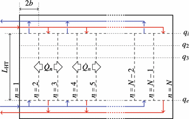
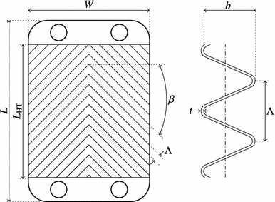
Heat transfer and pressure drop modelling
All heat exchangers were assumed to be of a plate type with a chevron corrugation. The working principle of a plate heat exchanger is depicted in Fig.
3
. As seen, a counter current arrangement was applied. The plate design may be seen in Fig.
4
and the plate dimensions are listed in Table
1
. A smaller plate size was applied for the IHEX and gas-cooler, due to the large difference in mass flow rate between the two streams. This will lead to a large pressure drop if the plate size is not reduced. Reducing the plate size increases the needed number of plates and thus, the cross-sectional area hence, reducing the flow velocity and, consequently, pressure drop.
Fig. 3
Principle sketch of the plate heat exchanger
Fig. 4
Plate dimension for chevron corrugated plates
For the IHEX and gas-cooler, the logarithmic mean temperature difference (LMTD) was applied [
18
]. For the absorber and desorber, the LMTD was not directly applicable, as enthalpy and temperature are not proportional [
21
]. Therefore, the LMTD was determined for each of the thirty steps of the absorber and desorber discretization. An average of the thirty values was applied to determine the heat transfer area. The overall heat transfer coefficient was found as the inverse of the sum of the average convective resistance of the hot and cold side and the conductive resistance in the material separating the two streams.
Palm and Claesson [
28
] reviewed several single- and two-phase heat transfer correlations for plate exchangers and suggested that Martin’s [
29
] is to be used. This is a semi-empirical correlation based on a heat transfer to friction analogy. Taboás et al. [
30
–
32
] investigate the two-phase flow of ammonia–water mixtures in plate heat exchanger during desorption. This work resulted in a correlation, which was applied in the present study.
No correlation directly addresses the two-phase flow of ammonia–water under absorption. Nordtvedt [
33
] suggested the use of the Silver [
34
], Bell and Ghaly [
35
] method. Here, the two-phase heat transfer coefficient was calculated based on: the heat transfer coefficient of the vapour phase, the heat transfer coefficient of the liquid film (corrected for two-phase flow effects) and the gradient of the equilibrium absorption curve.
A list of applied heat transfer and pressure drop correlations are stated in Table
2
, here, it is also indicated to which streams they were applied. Both heat transfer coefficient and friction factor, of the two-phase flows in the absorber and desorber, depend on the vapour quality,
q
. Therefore, an average of heat transfer coefficient and friction factor was determined based on a discretization in
q
. Twenty steps were applied.
Table 1
Plate dimension for absorber, desorber, gas-cooler and IHEX
Absorber and desorber
IHEX and gas-cooler
Lp (mm)
525
263
LHT (mm)
456
228
W (mm)
243
122
β (°)
60
60
Λ (mm)
9.6
9.6
b (mm)
2.5
2.5
t (mm)
0.4
0.4
λp (W/mK)
14.06
14.06
Table 2
Applied heat transfer and pressure drop correlations for the absorber, desorber, gas-cooler and IHEX
kth
Component
jth stream
Media
Heat transfer
Pressure drop
(3)
Gas-cooler
13
H2O
Martin [29]
Martin [29]
(3)
Gas-cooler
3
NH3/H2O
Martin [29]
Martin [29]
(5)
Absorber
12
H2O
Martin [29]
Martin [29]
(5)
Absorber
5
NH3/H2O
Vapour only:
Martin [29]
Liquid film:
Yan et al. [36]
Two-phase:
Silver [34], Bell and Ghaly [35]
Yan et al. [36]
(6)
IHEX
6 and 11
NH3/H2O
Martin [29]
Martin [29]
(8)
Desorber
15
H2O
Martin [29]
Martin [29]
(8)
Desorber
8
NH3/H2O
Liquid only:
Martin [29]
Two-phase:
Táboas et al. [30]
Táboas et al. [30]
Exergy analysis
To derive the exergy destruction in all components, the specific exergy of all streams was found. The specific exergy is the sum of two contributions: a physical part
ePH
, associated with reaching thermal and mechanical equilibrium with the dead state, and a chemical part
eCH
, associated with reaching chemical equilibrium with the dead state [
37
]. The definition of physical exergy is given by Eq. (
5
) [
18
]. Here,
hj,0
and
sj,0
are the specific enthalpy and entropy evaluated at the dead-state temperature and pressure and the chemical composition of the
j
th stream. The dead state in this study was chosen at
T0
= 25 °C and
p0
= 1.013 bar.
ejPH=hj-hj,0-T0sj-sj,0
The specific chemical exergy of the ammonia–water mixture was calculated using Eq. (
6
) [
18
,
38
]. Here,
eNH3CH
and
eH2OCH
are the standard molar chemical exergy of ammonia and water, respectively. At a temperature of 25 °C and pressure of 1.013 bar, these attain values of:
eNH3CH
= 336,684 kJ/kmol and
eH2OCH
= 45 kJ/kmol [
18
]. Further,
wXjrev
is the reversible specific work associated with the mixing of pure ammonia and pure water [
38
]. One value of specific chemical exergy was calculated for each of the three concentrations in the system,
xr
,
xl
and
xv
.
ejCH=xjeNH3CH+1-xjeH2OCH+wXjrevwXjrev=hj,0-xjhNH3,0-1-xjhH2O,0-T0sj,0-xjsNH3-1-xjsH2O,0
When the specific exergy of all streams was calculated the total exergy flow rate associated with each stream was determined as the product of the specific exergy of the
j
th stream and the stream mass flow rate:
E˙j=m˙jejPH+ejCH.
The control volumes surrounding the compressor and pump were assumed to be adiabatic and, therefore, exchange only mass and work. The remaining components were assumed to be surrounded by an adiabatic and zero-work boundary and thus, all transferred exergy was related to the transfer of material streams. For components in which an exergetic fuel and product can be defined, the exergy destruction was found as the difference between these:
E˙D,k=E˙F,k-E˙P,k
For these components, the product and fuel definitions may be seen in Table
3
.
Components such as the mixer and the throttling valve are dissipative components. Therefore, a meaningful exergetic fuel and product cannot be defined [
18
]. For these components, the exergy destruction was found by applying an exergy balance to the component control volume:
E˙D,4=E˙4+E˙11-E˙5E˙D,7=E˙7-E˙8
To evaluate the exergetic performance of the components, an exergy efficiency,
εk
, was defined, Eq. (
12
) [
18
]. Further, two exergy destruction ratios were used:
yk
and
yk∗
, Eqs. (
13
) and (
14
) [
18
]. Here,
yk
is the exergy destruction in the
k
th component relative to the total exergy fuel supplied to the system. While,
yk∗
is the exergy destruction in the
k
th component relative to the total exergy destruction in the system.
εk=E˙P,kE˙F,kyk=E˙D,kE˙F,totyk∗=E˙D,kE˙D,tot
Exergoeconomic analysis and optimization
Exergoeconomic analysis and optimization is a method for estimating and minimizing the total cost of a single component or an energy conversion system as a whole, over the course of its lifetime [
18
]. The objective of an exergoeconomic optimization is the minimization of the component or system product cost rate,
C˙P
.
Fig. 5
Graphical representation of the exergoeconomic optimum
Table 3
Definition of exergy fuel and product and fuel and product cost
kth
Component
E˙F,k=
E˙P,k=
C˙F,k=
C˙P,k=
Auxiliary relation
(1)
Compressor
W˙1
E˙3-E˙2
cwW˙1
C˙3-C˙2
(2)
Pump
W˙2
E˙10-E˙9
cwW˙2
C˙10-C˙9
(3)
Gas-cooler
E˙3-E˙4
E˙14-E˙13
C˙3-C˙4
C˙14-C˙13
c3=c4
(5)
Absorber
E˙5-E˙6
E˙13-E˙12
C˙5-C˙6
C˙13-C˙12
c5=c6
(6)
IHEX
E˙6-E˙7
E˙11-E˙10
C˙6-C˙7
C˙11-C˙10
c6=c7
(8)
Desorber
E˙15-E˙16
E˙1-E˙8
C˙15-C˙16
C˙1-C˙8
c15=c16
System
E˙F,1+E˙F,2+E˙F,8
E˙P,3+E˙P,5
C˙F,1+C˙F,2+C˙F,8
C˙P,3+C˙P,5
By the application of a cost balance [
18
], the product cost rate for a single component can be derived as:
C˙P,k=Z˙k+C˙F,k
Utilizing that:
E˙D=E˙F-E˙P
and
C˙D=cFE˙D
, this becomes:
C˙P,k=Z˙k⏟Investment+C˙D,k+cF,kE˙P,k⏟Operation
Equally for the system as a whole:
C˙P,sys=∑k=1KZ˙k⏟Investment+C˙D,sys+cF,sysE˙P,sys⏟Operation
As seen in Eqs. (
16
) or (
17
), the cost of the component or system product is comprised of three contributions, 1: the capital investment cost rate
Z˙
, 2: the exergy destruction cost rate
C˙D
and 3: the term
cFE˙P
. As indicated in Eqs. (
16
) and (
17
), the sum of
C˙D
and
cFE˙P
can be viewed as the operational cost of the component or system and will in the following be referred to as:
C˙OP=C˙D+cFE˙P
In the current study, the objective is the minimization of the cost of heat supplied by the HACHP and is thus a minimization of
C˙P,sys
, the definition of which is stated in Table
3
. The objective for the HACHP system can be stated as:
Objectivefunction:min∑k=1KZ˙k+C˙sysOP
The objective of the optimization is thus to balance the cost of capital investment with the cost of operation. From Eq. (
18
), it is clear that the cost of operation can be reduced by increasing exergy efficiency and consequently reducing the cost of exergy destruction,
C˙D,sys
. However, for most components, this will require an increased investment, e.g. for a heat exchanger, the exergy efficiency is increased if the temperature difference is reduced, consequently the heat transfer area and subsequently the investment must increase to adapt to the reduced temperature difference.
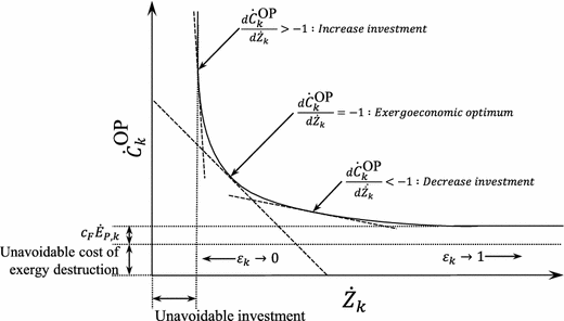
This behaviour is depicted in Fig.
5
. Here, it may be seen that the relation of
C˙kOP
to
Z˙k
has a horizontal and vertical asymptote. As the investment approaches infinity, some exergy destruction will prevail, due to technological limitations, this is known as the unavoidable exergy destruction [
39
]. Further, no matter how much the exergy efficiency is decreased, some investment will be needed, this is known as the unavoidable investment [
39
]. This behaviour is limiting for system improvement based on the conventional exergoeconomic analysis as this uses indicators based on absolute values of
C˙D
and
Z˙
and thus does not account for the unavoidable parts.
In the present study, cost functions for the component product equipment cost (PEC) were applied. Therefore, component investment costs were expressed mathematically, as a function of the HACHP design. This also allows the exergoeconomic optimum to be defined mathematically.
As seen in Fig.
5
, the exergoeconomic optimum choice of exergy efficiency,
εk
, is defined where the marginal cost rate of the levelized investment and maintenance cost,
Z˙k
, is equal to the marginal cost rate of operation,
C˙kOP
. Mathematically, this statement can be justified by taking the derivative of Eq. (
16
) with respect to the exergy efficiency,
εk
:
dC˙P,kdεk=dZ˙kdεk+dC˙kOPdεk
Thus, if
dZ˙kdεk=-dC˙kOPdεk
then
dC˙P,kdεk
= 0 and it can be confirmed that an optimum condition is attained. Further, if the component follows the behaviour seen in Fig.
5
, this optimum will be the global minimum for
C˙P,k
as:
C˙P,k→∞
for both
εk→=0
and
εk→=1
Hence, for a component that follows the behaviour seen in Fig.
5
, the cost of the component exergy product, Eq. (
16
), is minimized when:
dC˙kOPdZ˙k=-1
Subsequently, if:
dC˙kOPdZ˙k>-1-1 \end{aligned}$$\end{document}]]>
the total cost can be reduced by increasing the exergy efficiency, at the expense of an increased investment. Conversely, if:
dC˙kOPdZ˙k<-1
the total cost is reduced by reducing the investment, at the expense of a reduced exergy efficiency.
The design of the HACHP was governed by four decision variables. These were,
ΔTpp,k
for the absorber and desorber and
ϵk
for the IHEX and gas-cooler. A change in these variables will all exhibit the behaviour presented in Fig.
5
. It was the objective of the exergoeconomic optimization to determine the optimum values of these four variables. This was done by an iterative optimization procedure minimizing the objective function stated in Eq. (
19
).
Initial guess values for the four decision variables were made. Using the “Uncertainty Propagation” procedure in EES [
23
], the partial derivatives of both the investment cost rate,
Z˙Σ
and the operational cost rate,
C˙sysOP
, were found with respect to the four decision variables individually. The superscript
Σ
, here indicates the sum over all
K
components. Based on these partial derivatives, it was decided whether to increases or decrease the values. E.g. if:
∂C˙sysOP∂ΔTpp,5>∂Z˙Σ∂ΔTpp,5\left| \dfrac{\partial \dot{Z}^{\Sigma }}{\partial \Delta T_{\mathrm {pp,5}}}\right| \end{aligned}$$\end{document}]]>
the absorber pinch-point temperature difference should be reduced.
This procedure was repeated until:
∂C˙sysOP∂Z˙Σk∈-0.9,-1.1
for all the four decision variables simultaneously, at which an optimum was said to be attained.
To justify this approach, the results of the described procedure will, for one case, be compared to the result of a Genetic Optimization Algorithm maximizing the present value of the savings attained by the installation. The boundaries for the decision variables where set to:
ΔTpp∈{1;20}
and
ϵ∈{0;1}
. The Genetic Optimization Algorithm was performed with 32 individuals and 64 generations. The build in Genetic Optimization Algorithm in EES [
23
] was applied.
The yearly savings in operational costs attained by the installations was determined as:
Savingsyearly=Q˙HPhopcgas-celecCOP
Here,
cgas
and
celec
are the gas and electricity prices, respectively, and
hop
is the operating time per year. The present value of the savings, including the initial capital investment and maintenance cost, over the technical lifetime was then calculated as:
Savings=SavingsyearlyCRF-1.2·Investment
Here, CRF is the Capital Recovery Factor as given in [
18
], calculated based on the interest rate, inflation rate and technical lifetime stated in section “
Component investment cost and levelization
”. The factor of 1.2 accounts for the component maintenance cost as also discussed in section “
Component investment cost and levelization
”.
To conduct this optimization, the exergy cost rate,
C˙j
, of all streams was determined. This was done by applying cost balances to all components. A number of auxiliary relations were needed, these were determined based on the F-rule [
18
] and are listed in Table
3
. Further, it was assumed that the specific unit cost of exergy for the vapour stream and liquid stream exiting the separator were equal:
c2=c9
and that no cost was affiliated with the inlet condition of the sink and source:
c12=c15
= 0 €/s.
The definitions of the fuel and product costs, for the non-dissipative components and for the total HACHP system, are stated in Table
3
. Using these definitions, the component-specific fuel,
cF,k
and product,
cP,k
costs were determined, Eqs. (
28
) and (
29
).
cF,k=C˙F,kE˙F,kcP,k=C˙P,kE˙P,k
Further, the conventional exergoeconomic indicators were determined. These were the exergoeconomic factor,
fex
see Eq. (
30
), indicating the impact of the non-exergetic cost on the total cost and the relative cost difference,
r
see Eq. (
31
), indicating the relative increase in cost between the fuel and product of a component.
fex,k=Z˙kZ˙k+cF,kE˙D,krk=cP,k-cF,kcF,k
Component investment cost and levelization
PEC cost functions were developed based on Danish intermediate trade business prices [
40
,
41
] and individual producers [
42
]. Prices correspond to the year 2012. The cost functions were constructed as proposed by Bejan et al. [
18
]. A number of assumptions have been made to estimate the total investment of the HACHP system. These were as follows:
Total capital investment of a component was 4.16 higher than the PEC of the component [
18
].
PEC for a compressor was a function of the compressor displacement volume.
PEC for an electrical motor with a fixed efficiency was dependent only on the shaft power.
PEC for a heat exchanger was a function of the heat exchange area.
PEC of the pump was equivalent to its electrical motor.
PEC of the expansion valve, mixer and the liquid–vapour separator was neglected.
To determine the levelized capital component cost rates, the capital recover factor [
18
] was applied. An interest rate of 7 % and inflation rate of 3 % were assumed. Further, the technical lifetime was 15 years with 3000 operating hours per year. The component maintenance cost rate was assumed to be 20 % of the levelized capital cost rates. The total investment and maintenance cost rate (non-exergetic cost rate),
Z˙
, was the sum of the levelized capital investment and maintenance cost rate.
Electricity and natural gas prices correspond to an industrial process consumer in the Danish fiscal environment, prices were found in [
2
] and correspond to the year 2012.
Results
Thermodynamic analysis
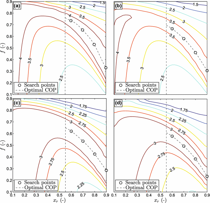
The ammonia mass fraction of the rich solution and the circulation ratio both have great influence on both the COP and the pressure levels in the system. As described by Jensen et al. [
5
] and Zamjlrescu [
43
], it is important to find the correct combination of these two parameters. Figure
6
shows the COP of the HACHP, as a function of the ammonia mass fraction and circulation ratio, with
ΔTpp,5=ΔTpp,8
= 10 K and
ϵ3=ϵ6
= 0.7. Figure
6
a is for a HACHP covering 10 % of the total heat load. Figure
6
b is for 15 %, Fig.
6
c for 20 % and Fig.
6
d is for 25 %. The solutions with
xr<0.55
are discarded, as these tend to result in sub-atmospheric desorber pressures and large volumetric flow rates in the compressor suction line [
5
]. It is seen, that for all four load shares, in the range of
xr>0.550.55$$\end{document}]]>
, one circulation ratio optimizes the COP for each value of
xr
. The optimum COP line for all four loads is shown with the dashed line. It can be seen that this line shifts downwards as the HACHP load is increased. Hence, the higher the load, the lower the circulation ratio. This is mainly due to the increased temperature glide in the heat sink.
Fig. 6
COP of the HACHP as function of
xr
and
f
for a HACHP covering
a
10 %,
b
15 %,
c
20 % and
d
25 % of the total heat load
Four points are chosen at each HACHP load, these are with
xr
of: 0.6, 0.7, 0.8 and 0.9 and the corresponding optimum circulation ratios. These points are indicated with circles on Fig.
6
.
Exergoeconomic optimization
The exergoeconomic analysis can then be applied to determine the exergoeconomic optimum design, at the 16 points derived from the thermodynamic analysis. Table
4
shows the result of the exergoeconomic analysis, at an initial set of guess values and at the exergoeconomic optimum. Both have a HACHP load of 15 % and a rich ammonia mass fraction
xr
= 0.8. The initial guess values are
ΔTpp,5=ΔTpp,8
= 15 K and
ϵ3=ϵ6
= 0.9.
Table 4
Non-exergetic and exergetic cost rates and exergoeconomic indicators for the initial guess and optimal solution for a HACHP with
xr
= 0.8 covering 15 % of the total heat load
kth
Decision var.
Z˙k+C˙D,k (cent/h)
fex,k (%)
rk (%)
∂C˙OP∂Z˙Σk
Initial guess variables
(1)
779
56
45
–
(2)
16.7
53
60
–
(3)
ϵ = 0.9−
351
8.3
62
−0.294
(4)
ΔTpp = 15 K
374
26
24
−2.02
(6)
ϵ = 0.9−
206
75
92
−0.263
(8)
ΔTpp = 15 K
74.8
100
–
−3.64
Objective function value, Eq. (19):
2896 cent/h
Present value of Savings, Eq. (27):
81,138 €
Exergoeconomic optimum by partial derivatives
(1)
728
57
48
–
(2)
15.7
54
61
–
(3)
ϵ = 0.864−
271
9.6
58
−0.933
(4)
ΔTpp = 11.3 K
387
44
26
−1.00
(6)
ϵ = 0.719−
76.6
53
54
−1.05
(8)
ΔTpp = 9.49 K
193
100
–
−1.02
Objective function value, Eq. (19)
2742 cent/h
Present value of Savings, Eq. (27):
138,078 €
Genetic optimization algorithm maximizing savings
(1)
728
57
48
–
(2)
15.7
54
61
–
(3)
ϵ = 0.864−
271
9.6
58
−0.965
(4)
ΔTpp = 11.3 K
387
44
26
−1.04
(6)
ϵ = 0.719−
76.6
53
54
−1.01
(8)
ΔTpp = 9.49 K
193
100
–
−0.979
Objective function value, Eq. (19):
2742 cent/h
Present value of Savings, Eq. (27):
138,117 €
As may be seen in Table
4
, for the initial guess values, the total cost rate for the gas-cooler is the third highest only surpassed by the compressor and absorber. The gas-cooler also has the second highest relative cost difference. Judging from the low exergoeconomic factor, conventional exergoeconomic optimization states that the investment should be increased, but judging from the partial derivative the investment should actually be decreased to reduce the overall cost.
This difference arises, as the partial derivatives account for both the interdependencies between component exergy efficiencies and for the unavoidable part of exergy destruction and investment.
In the case of the absorber and IHEX, it may be seen that the conclusions of the conventional exergoeconomic analysis and the partial derivatives coincide.
The exergoeconomic factor for the desorber is
fex,8=1
. This is because no cost is associated with the waste heat and thus,
cF,k=0
. Therefore, the relative cost difference cannot be calculated as,
cF,k
is the fraction denominator. This makes it hard to judge whether or not the choice of the design parameter for the desorber is appropriate. However, judging from the partial derivative, it is clear that savings to the overall cost can be attained by increasing the desorber exergy efficiency.
The conclusion from the partial derivatives of the initial guess is that: The effectiveness of the IHEX and gas-cooler should be reduced to lower the investment, the IHEX effectiveness should be lowered more than for the gas-cooler. Further, the absorber and desorber pinch-point temperature difference should both be reduced, more for the desorber than for the absorber.
Table
4
states the cost rates and exergoeconomic indicators at the optimum values of the decision variables, suggested by the partial derivatives. Here, the absorber and desorber pinch-point temperature differences are reduced to
ΔTpp,5=11.3
K and
ΔTpp,8=9.49
K, respectively. The IHEX effectiveness is reduced to
ϵ6=0.719
and the gas-cooler effectiveness to
ϵ3=0.864
. Hence, the direction and the magnitude of the change in variables are consistent with the conclusion of the partial derivatives from the initial guess. Further, it can be seen that only the exergoeconomic factor and relative cost difference of the IHEX undergo substantial change between the initial guess and the optimum.
The present value of the savings attained by the HACHP is 81,138 € with the initial guess values. This is increased by 70 %, at the exergoeconomic optimum, to a value of 138,078 €. The physical variables of the HACHP process, for the exergoeconomic optimum from Table
4
, are listed in Table
5
.
Table 5
Thermodynamic state point variables for the exergoeconomic optimum seen in Table
4
,
xr
= 0.8 and 15 % of the total heat load covered by HACHP
jth
m˙j (kg/s)
pj (bar)
Tj (°C)
xj (−)
hj (kJ/kg)
sj (kJ/kgK)
vj·10-3 (m3/kg)
ePH (kJ/kg)
eCH (kJ/kg)
1
1.387
13.32
64.25
0.8000
776.4
2.802
61.10
220.6
15,875
2
0.7490
13.32
64.25
0.9947
1386
4.518
112.0
360.0
19,764
3
0.7490
49.10
196.6
0.9947
1665
4.638
41.99
603.2
19,764
4
0.7490
49.10
125.6
0.9947
1428
4.106
31.77
524.5
19,764
5
1.3870
49.10
119.5
0.8000
857.6
2.753
15.27
316.4
15,875
6
1.3870
49.10
100.6
0.8000
354.9
1.433
1.712
207.2
15,875
7
1.3870
49.10
90.09
0.8000
298.7
1.28
1.662
196.6
15,875
8
1.3870
13.32
45.37
0.8000
298.7
1.343
21.61
177.8
15,875
9
0.638
13.32
64.26
0.5714
60.57
0.7866
1.394
56.27
11,311.4
10
0.638
49.10
65.27
0.5714
66.48
0.7901
1.319
61.12
11,311.4
11
0.638
49.10
90.91
0.5714
188.5
1.138
1.385
79.55
11,311.4
12
7.889
5.000
85.00
–
356.3
1.134
–
23.00
–
13
7.889
4.971
106.0
–
444.7
1.374
–
40.00
–
14
7.889
4.674
111.3
–
467.2
1.433
–
45.00
–
15
7.889
5.000
75.00
–
314.3
1.015
–
16.00
–
16
7.889
4.978
54.93
–
230.4
0.7668
–
6.000
–
Further, the results of a Genetic Optimization Algorithm maximizing the present value of the savings are presented. The Genetic Optimization Algorithm was given the same initial guess as provided to the exergoeconomic optimization. As seen from Table
4
, the Genetic Optimization Algorithm finds the same decision variables as found by the exergoeconomic optimization, which suggests that the applied optimization procedure is capable of determining the true optimum. It is seen that the Genetic Optimization Algorithm finds a savings that is 0.3 % higher than what is attained by the exergoeconomic optimization. However, the partial derivatives also suggest that the solution found by the Genetic Optimization Algorithm is closer to the exergoeconomic optimum. The exergoeconomic approach using partial derivatives found the four optimum decision variables after five iterations, each with a computation time of approximately 1 min. While the computation time for the Genetic Optimization Algorithm was several hours.
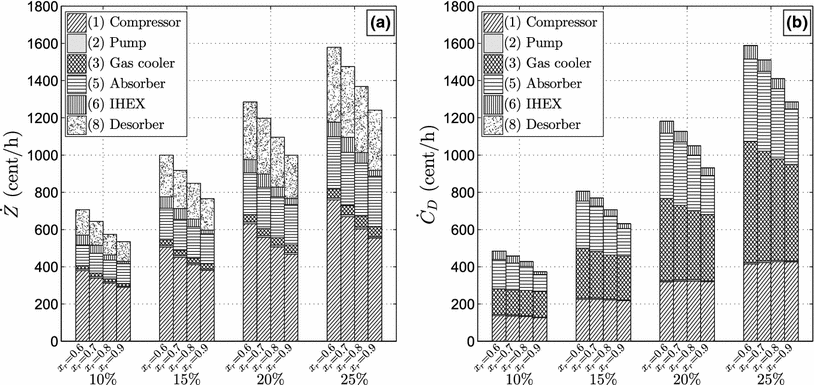
This optimization procedure has been conducted for all of the 16 design configurations. Figure
7
a shows the non-exergetic cost rate,
Z˙k
, for the components at all 16 optimal designs. Figure
7
b shows the exergy destruction cost,
C˙D,k
. It may be seen that the total non-exergetic cost rate,
Z˙Σ
, increases when decreasing the ammonia mass fraction. This is caused by an increase in the compressor, IHEX and desorber
Z˙k
. The remaining components are indifferent to the change in ammonia mass fraction. The compressor
Z˙k
increases the most. This is caused by the reduced vapour pressure of the working fluid, resulting in an increased displacement volume. The IHEX
Z˙k
is increased due to the increased circulation ratio for reduced ammonia mass fractions. Thereby, the capacity rates of the rich and lean mixtures approach each other, consequently reducing the LMTD and increasing the needed heat load. Both resulting in the need for an increased area. Figure
7
a also shows that the total non-exergetic cost rate,
Z˙Σ
increases when the heat pump load is increased. The marginal
Z˙Σ
is close to constant.
From Fig.
7
b, it is seen that the total exergy destruction cost,
C˙DΣ
, increases when decreasing the ammonia mass fraction. It is seen that the cost of operating the compressor is not significantly influenced by the ammonia mass fraction. Further, the gas-cooler
C˙D,k
, is indifferent to
xr
for HACHP loads of 10 and 15 %. For the absorber and IHEX, the
C˙D,k
is increased, when decreasing the ammonia mass fraction. For the absorber, this is caused by the degradation of the two-phase heat transfer coefficient. The reduced heat transfer coefficient shifts the optimal size of the absorber to a lower exergy efficiency. For the IHEX, the increased
C˙D,k
is caused by the increased circulation ratio. For the desorber,
C˙D,k
decreases when the ammonia mass fraction is reduced. This, in spite of the decreased heat transfer coefficient. This is caused by the interdependency between the low pressure and the compressor investment, as a larger desorber investment can reduce the compressor investment by increasing the suction line pressure. The total exergy destruction cost,
C˙DΣ
, increases with the delivered heat load. The marginal
C˙DΣ
is also increased with the heat load.
Fig. 7
Zk˙
(
a
) and
C˙D,k
(
b
) of the
k
th component at HPLS of 10, 15, 20 and 25 % and
xr
of 0.6, 0.7, 0.8 and 0.9
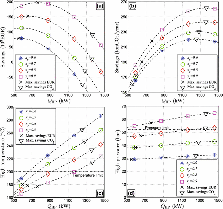
HACHP implementation, economic and environmental savings
Several issues govern the implementation of the HACHP. As shown in Fig.
7
, both the choice of ammonia mass fraction and heat pump load influence the investment and the operating costs of the HACHP.
Fig. 8
a
Present value of the economic savings.
b
Yearly CO
2
emission savings.
c
Compressor discharge temperature.
d
Compressor discharge pressure. All shown a function of the design heat pump load and ammonia mass fraction
To estimate yearly CO
2
emissions, the fuel-specific emission factors for electricity and natural gas in the Danish energy system are used [
2
].
Figure
8
shows the economic and CO
2
savings as well as the compressor discharge temperature and pressure. All are shown as a function of the HACHP load
Q˙HP
. The values are given for the exergoeconomic optimum designs. Figure
8
a shows the present value of the economic savings in Euro. As can be seen: for each ammonia mass fraction, one heat pump load maximizes the savings. At this point, the marginal total cost of the HACHP (sum of investment and operation) is equal to the marginal cost of gas heating. As seen, the higher the ammonia mass fraction, the higher the savings and the higher the optimum HACHP load. Figure
8
b shows the yearly CO
2
emissions savings. It can be seen that the maximum emission savings occur at a higher HACHP load than the maximum economic savings. Further, it is seen that, the higher the ammonia mass fraction, the higher the emissions savings.
Figure
8
c shows the compressor discharge temperature and the temperature limit. It can be seen that none of the economic optimum loads are restricted by the temperature limit, while all of the optimum emission loads exceed this constraint. Further, it can be seen that increasing the ammonia mass fraction decreases the compressor discharge temperature. Figure
8
d shows the compressor discharge pressure. Here, it can be seen that only the optimal savings for
xr=0.9
is restricted by the pressure limit. Further, it can be seen that increasing the ammonia mass fraction increases the discharge pressure.
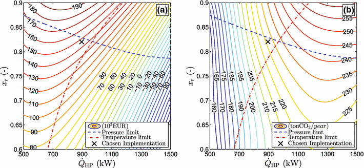
As the best possible implementation of the HACHP may be one with an ammonia mass fraction between the curves shown in Fig.
8
, an interpolation between HACHP load and the ammonia mass fraction for the 16 exergoeconomic optimum points has been made.
Figure
9
a shows the interpolation of economic savings with the pressure and temperature limits imposed. The area below the blue-dashed line satisfies the pressure constraint, while the area to the left of the red dash-dot line satisfies the temperature constraint. A similar plot for the emission savings is shown in Fig.
9
b. The chosen implementation is indicated by the
×
. This is chosen to attain both high economic and emission savings. The chosen load is
Q˙HP=895
kW with an ammonia mass fraction 0.82. The circulation ratio is then 0.43. The exergoeconomic optimum values of pinch-point temperature difference and effectiveness are:
ΔTpp,5=11.2
K,
ΔTpp,8=8.98
K,
ϵ6=0.730
and
ϵ3=0.864
. Here, the present value of the saving is 146,426 € and the yearly CO
2
emissions are reduced by a total 227 ton.
Table
6
shows the results of the exergy and exergoeconomic analysis of the chosen implementation. As seen, the highest contribution to the exergy destruction in the system is caused by the compressor and the throttling valve, both accounting for 22 % of the total exergy destruction. The gas-cooler, absorber and desorber are the other main contributors, responsible for 17, 16 and 15 %, respectively. The component with the highest total cost rate is the compressor, while this component has the second lowest relative cost difference. The highest relative cost difference is found in the gas-cooler.
Fig. 9
a
Interpolation of the economic savings.
b
Interpolation of the emission savings. Both as a function of the design heat load and ammonia mass fraction and with compressor discharge pressure and temperature limit imposed
Table 6
Results of the exergy and exergoeconomic analysis of the chosen implementation
kth
Component
E˙P,k (kW)
E˙F,k (kW)
E˙D,k (kW)
εk (%)
yk (%)
yk∗ (%)
Z˙k (cent/h)
C˙D,k (cent/h)
fex,k (%)
rk (%)
1
Compressor
187
226
38.7
83
13
29
415
322
56
47
2
Pump
2.99
3.82
0.830
78
0.27
0.63
8.35
6.92
55
61
3
Gas-cooler
40.3
61.3
21.0
66
6.8
16
27.6
253
10
58
4
Mixer
–
–
4.95
–
1.6
3.7
27.2
–
–
0
5
Absorber
136
154
18.0
88
5.8
14
172
214
45
26
6
IHEX
11.4
14.3
2.95
79
0.95
2.2
38.8
35.5
52
54
7
Throttling valve
–
–
26.7
–
8.6
20
0
–
–
–
8
Desorber
59.8
79.4
19.6
75
6.3
15
190
0
100
–
Discussion
In the present study, partial derivatives were applied as an aid to determine the exergoeconomic optimum of the HACHP, which proved to be a helpful tool. However, this approach was only applicable due to the application of cost functions. Thereby, the investment cost of a component was linked mathematically to the choice of the design variables, which allows the numerical partial derivatives to be determined. In real-life applications, this is hardly ever the case, wherefore, the partial derivatives cannot be attained. In these cases, the advanced exergoeconomic analysis, as applied in [
44
], could be used. The advanced exergoeconomic method can explicitly determine the unavoidable costs of both investment and operation and component interdependencies and does not require the application of cost function. The advanced exergoeconomic method does not constitute a mathematical optimization procedure, but defines the best possible design as one at which the advanced exergoeconomic factors for all components are 50 %. The advanced exergoeconomic factor is calculated as seen in Eq. (
30
), but subtracts the unavoidable parts of
Z˙k
and
C˙D,k
shown in Fig.
5
. Thus, if the advanced exergoeconomic factor is close to 50 %, it is likely that the design is close to the exergoeconomic optimum.
Further, the use of cost functions would allow the application of any mathematical optimization procedure to maximize the savings, without the use of exergy or exergoeconomics. This approach would, however, not yield the detailed information on the sources of investment and operational cost that is attained with the exergoeconomic analysis.
This information is gathered in Table
6
and from this, insight to how the HACHP can be further improved is attained. As can be seen in Table
6
, the gas-cooler accounts for both a significant part of the exergy destruction cost rate and also has the highest relative cost difference. The high cost rate and relative cost difference are caused by the superheat of the gas exiting the compressor. This cannot be changed directly by changing the design of the gas-cooler, but could be reduced by the implementation of a two-stage compression. This could also reduce the exergy destruction cost of the compression. Therefore, this could prove to be a good improvement of the system.
Ommen et al. [
12
] tested ammonia mass fractions of 0.7 and 0.9 and also found the total cost to increase with the reduction of ammonia mass fraction. The optimum pinch-point temperatures found in [
12
] are significantly lower that those presented in the current study. This is assumed to be caused by the use of constant overall heat transfer coefficient applied in [
12
]. Hence, the degradation of two-phase heat transfer due to mass diffusion resistance is not captured. This has been shown to have an influence on both the PEC and the exergoeconomic optimum design and should be accounted for.
Conclusion
The implementation of a HACHP in a spray-drying facility was investigated and optimized. Heat transfer and pressure drop correlations from the open literature were gathered and implemented in the thermodynamic model of the HACHP. Cost functions based on Danish intermediate trade price were constructed to assess the heat pump investment. The exergoeconomic method has been used to minimize the total cost of the HACHP. The influence of ammonia mass fraction, circulation ratio and heat pump load was also investigated. Constraints based on commercially available technologies were imposed.
The best possible implementation was found to be a 895 kW HACHP with an ammonia mass fraction of 0.82 and circulation ratio of 0.43. This resulted in an economic saving with a present value of 146.426 € and a yearly reduction of the CO
2
emissions by 227 ton.
The use of numerical partial derivatives was applied to implicitly account for the unavoidable costs and component interdependencies. This gave a more precise indication of the exergoeconomic optimum compared to what is attained based only on the exergoeconomic indicators: exergoeconomic factor and relative cost difference. However, the exergoeconomic indicators still gave valuable insight of the sources of investment and the cost of irreversibilities. The indicators gave useful information to the further improvement of the system.
Acknowledgments
This research project is financially funded by EUDP (Energy Technology Development and Demonstration). Project title: “Development of ultra-high temperature hybrid heat pump for process application”, Project Number: 64011-0351.
References
Baker and McKenzie (2005) Energy consumption of industrial spray dryers 23(1–2) (pp. 365-386) 10.1081/DRT-200047665
Unknown ()
Brunin et al. (1997) Comparison of the working domains of some compression heat pumps and a compression–absorption heat pump 20(5) (pp. 308-318) 10.1016/S0140-7007(97)00025-X
Unknown ()
Unknown ()
Unknown ()
Unknown ()
Unknown ()
Prasertsan and Saen-saby (1998) Heat pump dryers: research and development needs and opportunities 16(1–2) (pp. 251-270) 10.1080/07373939808917402
Gungor et al. (2011) Exergoeconomic analyses of a gas engine driven heat pump drier and food drying process 88(8) (pp. 2677-2684) 10.1016/j.apenergy.2011.02.001
Chua et al. (2002) Heat pump drying : recent developments and future trends 20(8) (pp. 1579-1610) 10.1081/DRT-120014053
Hultén and Berntsson (2002) The compression/absorption heat pump cycle—conceptual design improvements and comparisons with the compression cycle (pp. 487-497) 10.1016/S0140-7007(02)00014-2
Hultén and Berntsson (1999) The compression/absorption cycle—influence of some major parameters on COP and a comparison with the compression cycle (pp. 91-106) 10.1016/S0140-7007(98)00047-4
Bejan et al. (1996) Wiley-Interscience publication
Kotas (1985) Butterworths
Kemp (2005) Reducing dryer energy use by process integration and pinch analysis 23(9–11) (pp. 2089-2104) 10.1080/07373930500210572
Itard and Machielsen (1994) Considerations when modelling compression/resorption heat pumps 17(7) (pp. 453-460) 10.1016/0140-7007(94)90005-1
Zheng et al. (2013) Theoretical and experimental investigations on the changing regularity of the extreme point of the temperature difference between zeotropic mixtures and heat transfer fluid (pp. 541-552) 10.1016/j.energy.2013.02.029
Unknown ()
Unknown ()
Unknown ()
Thorin (2001) Thermophysical properties of ammonia water mixtures for prediction of heat transfer areas in power cycles 1 22(1) (pp. 201-214) 10.1023/A:1006745100278
Nekså et al. (1998) CO2-heat pump water heater: characteristics, system design and experimental results 21(3) (pp. 172-179) 10.1016/S0140-7007(98)00017-6
Palm and Claesson (2006) Plate heat exchangers: calculation methods for single and two-phase flow (pp. 88-98) 10.1080/01457630500523949
Martin (1996) A theoretical approach to predict the performance of chevron-type plate heat exchangers 35(4) (pp. 301-310) 10.1016/0255-2701(95)04129-X
Táboas et al. (2012) Assessment of boiling heat transfer and pressure drop correlations of ammonia/water mixture in a plate heat exchanger 35(3) (pp. 633-644) 10.1016/j.ijrefrig.2011.10.003
Táboas et al. (2010) Flow boiling heat transfer of ammonia/water mixture in a plate heat exchanger 33(4) (pp. 695-705) 10.1016/j.ijrefrig.2009.12.005
Táboas et al. (2007) Pool boiling of ammonia/water and its pure components: comparison of experimental data in the literature with the predictions of standard correlations (pp. 778-788) 10.1016/j.ijrefrig.2006.12.009
Unknown ()
Unknown ()
Unknown ()
Yan et al. (1999) Condensation heat transfer and pressure drop of refrigerant R-134a in a plate heat exchanger 42(6) (pp. 993-1006) 10.1016/S0017-9310(98)00217-8
Bejan (2006) Wiley
Morosuk and Tsatsaronis (2008) A new approach to the exergy analysis of absorption refrigeration machines 33(6) (pp. 890-907) 10.1016/j.energy.2007.09.012
Tsatsaronis and Park (2002) On avoidable and unavoidable exergy destructions and investment costs in thermal systems 43(9–12) (pp. 1259-1270) 10.1016/S0196-8904(02)00012-2
Unknown ()
Unknown ()
Unknown ()
Zamjlrescu (2009) Modeling and optimization of an ammonia–water compression–resorption heat pumps with wet compression 33(1) (pp. 75-88)
Morosuk et al. (2012) Advanced exergy-based analyses applied to a system including LNG regasification and electricity generation10.1186/2251-6832-3-1