Institute of Fluid-Flow Machinery, Polish Academy of Sciences, Gdansk, PL
Abstract
The syngas purification is a basic problem in the gas production process through the biomass gasification. This issue is important due to the use of the Venturi scrubbers in the syngas cleaning process. As it is commonly known, syngas is an alternative for the coal and using syngas instead of the coal leads to ‘clean energy’ generation. The paper concerns the analytical research studies on two-phase fluid flow pattern in Venturi’s throat. The uniform coverage of Venturi’s cross-section with small droplets plays a significant role in the dust particles collection and chemicals removal as Venturi’s cleaning efficiency mostly depends on this operation parameter. Therefore, the analysis of the two-phase fluid flow with respect to a droplet deposition and entrainment was carried out. Based on these research studies, it is possible to determine the variation of the liquid superficial velocity in the core of the flow and within the liquid wall film, the length at which the droplet entrainment starts to occur, the liquid fraction variation with Venturi’s throat length and diameter. The obtained analytical model, which is introduced in the paper, was validated with the use of the experimental data available in the literature.
Introduction
Bearing in mind the concern for dust and chemical pollutions removal from the atmosphere, searching of a so-called clean energy sources is obligatory. The Polish power system mostly relies on the carbon power plants thus Poland is struggling with the greenhouse gases (GHG) and dust particles high emission problem. Even though some works enabling carbon dioxide capture and flue gas purification are being undertaken, the problem is still not being sufficiently solved [
1
]. In the light of this fact, the alternative heat carriers ought to be searched by researchers. The greenhouse gases emission reduction is a critical problem of the world which scientists should work on. Thus works on alternative fuels are of a highest importance [
2
]. The synthesis gas (syngas), which can be produced through the biomass gasification process, seems to be a very attractive alternative to coal. However, syngas also needs to be purified from different chemicals and dust particles so it could cope the particular restrictions in the last step of its processing which is a key factor in its production technology. According to the literature [
3
,
4
,
5
,
6
–
7
], Venturi scrubbers are being widely used in the syngas purification process and biohazard materials cleanup, and others as these devices are found to be very attractive from both, efficiency and economical, points of view. Thus, authors have decided to propose an innovative analytical model for Venturi throat two-phase fluid flow pattern description which further can be used for Venturi designing methods refinement. Worth mentioning is the fact that in the current paper there are presented the preliminary studies in this field, and works are going to be continued. In the studied case, the two-phase two-component fluid flow is present in Venturi’s throat of a cylindrical shape. The gas (air) is a continuous phase, and the sorption liquid (water) is a dispersed phase. Thus, there occurs an annular flow with water as liquid wall film and a homogenous mixture in the core of the flow. The content of the solid particles has been omitted in the current considerations. It is obvious that the two-phase flow, its description and analysis is much more difficult, regarding the physics, than a single-phase flow. In the two-phase flow apart from inertia, viscosity and pressure forces present in a single-phase flow, there also occur surface tension forces. Additionally, wetting the internal lateral surface of the channel results in a liquid wall film forming. From one hand, the liquid wall film improves the droplet deposition but its existence also allows for drops entrainment. As a consequence of the mentioned interactions the equations of the movement of both phases are unstable. The two-phase flow pattern plays a significant role in the studied problem of a syngas cleaning process, thus the regimes of this flow cannot be neglected nor disregarded.
Literature review
For several decades, scientists have been conducting research into the effectiveness of Venturi scrubbers to remove pollutants form gas. In the construction of the Venturi scrubbers, there are known three different methods of liquid injection: as a film, as a jet and as a spray. The liquid is introduced as a spray in the ejector type Venturi scrubber which is discussed in works [
8
,
9
–
10
] whereas sorption liquid injected as a jet is typical for a Pease-Anthony Venturi scrubber which is studied in works [
11
,
12
,
13
,
14
,
15
–
16
]. Gonçalves et al. [
11
] have presented a mathematical description of the trajectory of the injected liquid. The model takes into account the penetration of the liquid stream and its separation. This description was used by the authors in another article [
12
] to determine the distribution of droplets density. The use of the Venturi scrubber in which a stream of a liquid is sprayed perpendicular to the throat, at the subsonic gas flow, finds many applications in various industrial processes such as combustion, evaporative cooling or in the medical and agricultural devices. However, the model described in the paper [
11
], although it may find many applications in other types of scrubbers, according to the statement of the authors of this paper, is not valid for the scrubber used for the gas dedusting. The article [
12
], which is a continuation of the paper [
11
], focuses on the theoretical and experimental analysis of the droplets density distribution in the horizontal Venturi scrubber with rectangular cross-section. This issue is very important from the scrubber's efficiency point of view which depends on the liquid atomizing. By ensuring proper distribution of the liquid, greater gas dedusting efficiency can be achieved with a minimum water consumption. The researches were conducted for variable throat length. The liquid was injected through one hole, perpendicular to the throat which enabled the studies on the effect of penetration of the liquid stream on the droplets dispersion. In the article [
12
], a mathematical model from the paper [
11
] was used and developed. Unlike to article [
11
], the subject of considerations in the paper [
12
] is the Venturi Pease-Anthony scrubber, used to remove particles in the micron range. A very important aspect is the aforementioned liquid atomizing. In the scrubbers, where the droplets concentration is sometimes higher or lower, it has been observed that the purification process is not that effective as in the scrubbers in which the droplets density distribution in the throat area is approximately constant. Venturi scrubbers with liquid injected as a wall film through the confusor inlet, or as a jet, is the subject of investigations in the following works [
5
,
15
,
17
,
18
,
19
–
20
]. The dynamics of mechanisms during the gas dedusting process in the Venturi scrubber, regardless of the method of liquid injection, is expressed by the pressure drop. One of the simplest pressure drop prediction model was proposed by Calvert [
21
]. The model assumes a one-dimensional, incompressible and adiabatic flow in which all the liquid is atomised into droplets of equal size. In addition, the Calvert model [
21
] assumes droplet acceleration to the gas velocity at the end of the throat while the effect of the gas acceleration in the throat and the wall friction are neglected. The preliminary Calvert model [
21
] was improved by Yung [
22
] (assuming that the droplet velocity at the end of the throat will not be equal to the gas velocity), and Leith [
23
] (which takes into account the relative slowdown of the droplets in the diffuser). Other simple models of the pressure drop prediction are the Hesketh [
24
] and the Boll [
25
] models from which the first one assumes that droplets accelerate and finally reach the gas speed in the throat. The latter model [
25
] includes the gas and droplets acceleration and the friction and assumes the fully atomised liquid. The model of Azzopardi and Govan [
26
] was improved in works [
27
,
28
–
29
] in which the growth and detachment of the gaseous boundary layer was determined. Obviously, regardless to the liquid injection method, a liquid wall film forms on the channel wall which more or less affects the overall pressure drop and the gas dedusting efficiency which was considered in papers [
24
]–
27
. The two-phase flow annular pattern was also considered in works of Viswanathan et al. [
8
,
30
] in which the thickness of the liquid wall- film against the overall Venturi orifice length was determined. Additionally, the velocity of a liquid wall film and the pressure drop were estimated in a wide range of the Venturi operation conditions. The model of Azzopardi and Govan is described in papers [
5
,
26
] and [
9
]. Azzopardi and Govan took into account the entrainment and deposition of the droplets and the growth of the gaseous boundary layer in the diffuser area to correctly predict the pressure drop. This model correctly explained that the excess pressure recovered from the previous models was a result of the increase of the gaseous boundary layer in the diffuser. Azzopardi and Govan [
5
] presented a one-dimensional model describing the flow of both liquid, dust and the gas. All previous Authors of models, like a Yung, Boll, Calvert, Miheisi, Chongvisal, Holland and Goel, Placek, Peters and Bayvel, as well as others, have considered the flow of the liquid only in a droplet form, and in the meantime, a liquid film is always formed on the walls of the scrubber, and it has a significant impact on the purification process [
5
], as it is discussed in this article. In addition, under certain conditions, when the dust exhibits particular adhesiveness or when there is a problem with a throat erosion, caused by a high velocity of the gas flow, the liquid can be intentionally injected as a film onto the channel walls and then atomized by the gas. Neglecting the existence of the liquid film on the walls of the scrubber, as it is usually done, some important factors are being ignored. First of all, the liquid that flows as a liquid film is not in the form of drops, so it does not take a part in the gas purification process. Secondly, the liquid film will behave like a rough surface in direct contact with the flowing gas which will increase the pressure drop due to friction. Thirdly, due to the presence of a liquid film along the entire length of the Venturi orifice, there will be a constant accumulation of droplets on the wall and their entrainment. Therefore, there will be new droplets of a velocity lower than the gas so they will be used effectively in the gas cleaning process. The model presented by Azzopardi and Govan [
5
] takes into account the flow of a part of the liquid in the form of a film on the wall, as well as the transition between the droplets and the liquid film. The paper describes a model of the annular flow which is based on the equation describing the variation of the liquid wall film mass flow rate, resulting from the droplets deposition and entrainment. An important discovery by Ekman, Johnstone and Muir and others were that the efficiency of the Venturi increases with the increase of the gas to liquid ratio at a constant pressure drop [
5
]. In the article [
31
], attention was drawn to the fact that the spatial distribution of the droplets and their size have a very large impact on the pollutants removal efficiency. The spatial distribution of the droplets began to be considered to improve the prediction model of the purification efficiency.
Analytical model of the two-phase flow in Venturi’s throat
Authors of the paper have carried out a theoretical study on the two-phase air–water flow pattern in Venturi’s throat. In the analytical one-dimensional model presented in the paper, it was assumed that the liquid flows as droplets in the core of the flow and also as a film on the wall. In the case of the two-phase flow pattern presented in the paper, neglecting the liquid wall film flow results in lowering the correctness of the model. As it was mentioned by Azzopardi et al. [
5
], liquid film existing on the channel wall doesn’t take a part in the chemical pollutants removal and dust collection until there occurs the droplet entrainment from the wall film to the core of the flow. Additionally, the droplets which entrain from the liquid film flow to the two-phase core-flow have smaller velocity thus the pollutant removal efficiency increases [
5
]. Moreover, the liquid wall film affects the friction component of the momentum equation of the two-phase flow thus neglecting the liquid wall film results in incorrectness [
5
]. Current investigations based on the authors’ analytical model have led to the estimation of the pressure drop along Venturi’s throat and liquid fraction in the flow. The introduced authors’ model allows for the pressure drop calculation with the use of the core-flow parameters which are listed further in the paper. Additionally, the model allows to define the mass flux of the liquid film at the channel walls and the mass flow rate of the liquid in the core of the flow. Present model takes into consideration two important phenomena existing in the two-phase flow. Namely, the deposition of the liquid droplets within the liquid wall film and the entrainment of the drops from the wall film to the core of the two-phase fluid flow. The two-phase flow present in Venturi’s throat is a homogeneous air–liquid droplets mixture in the core of the flow and a liquid film at the channel wall. The total liquid (water) and gas (air) mass flow rates are given, and the superficial liquid velocities in the core of the flow and in the liquid wall film are the resultant ones. Obviously, the two-phase flow is being also characterized by the momentum exchange between both phases due to which the motion of the one phase may strongly affect the other’s flow. In the current preliminary studies, momentum exchange through a phase separation boundary was estimated, however, it was not included into calculus as the liquid content is low. Consequently, the calculation results have shown that momentum transfer can be neglected in the current analytical research studies. However, for highest values of the liquid to air ratio, it must be included as the shear stresses, resulting from the momentum exchange, also influence the value of the pressure drop.
As illustrated in the Fig.
1
, the following balance equation of the liquid film mass flow rate can be written:
m˙f=m˙f+dm˙f-D-E·π·d·dz
Fig. 1
Illustration of the studied two-phase flow in Venturi’s throat with
dm˙f=-dm˙c
,
m˙l=const
and
m˙ν=const
and hence
dm˙fdz=D-E·π·d,
where
m˙f
[kg/s] is the liquid mass flow rate at the lateral wall of Venturi’s throat,
D
[kg/(s m
2
)] is a deposition rate,
E
[kg/(s m
2
)] is an entrainment rate,
d
[m] is diameter of Venturi’s throat, and
z
[m] is Venturi’s throat length. The total flow mass balance equation is defined as
m˙=m˙v+m˙c+m˙f,
where
m˙c
[kg/s] is the liquid droplets mass flow rate in the core of the flow,
m˙v
[kg/s] is the inlet mass flow rate of the vapour. Dividing Eq. (
3
) by Venturi’s cross-section area,
A
[m
2
], leads to the following equation:
G=Gv+Gc+Gf,
where
G
[kg/(s m
2
)] is the mass flux of the main flow;
Gv
[kg/(s m
2
)] is the vapour mass flow rate referred to Venturi’s throat cross-section area,
Gc
[kg/(s m
2
)] is the liquid droplets mass flow rate in the core of the flow referred to Venturi’s throat cross-section area,
Gf
[kg/(s m
2
)] is the liquid mass flow rate of the liquid film at the wall referred to Venturi’s throat cross-section area. The mass balance equations for the core of the flow and the flow within the liquid wall film are defined through the following equations taken from [
32
]:
dGfdz=4d·D-E,dGcdz=4d·-D+E
Equation (
5
) was first proposed by Whalley [
31
], however, he has included the heat flux term which is skipped in Eq. (
5
) as heating of the channel walls is not being considered in the current paper.
The Eqs. (
5
) and (
4
) can be written in the following non-dimensional form
dGf+dz+=4·D+-E+Gc++Gf++Gν+=1,
where ‘
+
’ refers to the non-dimensional variable. The innovative concept presented in the paper is about solving this particular set of equations (Eq. (
8
)) which hasn’t been solved in the literature so far. However, the analysed two-phase flow character is very similar to the one which occurs during the boiling crisis regarding the hydrodynamics of the flow [
32
,
33
]. In the case of the boiling crisis, there occur the liquid wall film dryout. This is an opposite phenomenon to the one being investigated in this paper as in the current work the liquid wall film formation is being considered. The mentioned set of equations may contain Eqs. (
6
) or (
5
), as these equations differ only by the sign, and Eq. (
4
). In the research studies shown in the paper, the set of Eqs. (
5
) and (
4
) was considered.
In accordance with [
32
], it was assumed that
E+=K·C·Gf+,D+=C·Gc+,
where
K
is determined from the experimental data presented in [
34
],
C
is estimated further in the text as
C1,C2
and its general form is introduced through
Ck
.
The deposition rate can be determined by the following formula [
32
,
35
,
36
]:
D=k·cdc,
where
cdc
[kg/m
3
] is the concentration of the liquid droplets in the core of the flow,
k
[m/s] is the deposition mass transfer coefficient.
The model described by Whalley was incorporated into the Harwell annular flow modelling code HANA in which the simplified correlations for deposition Eq. (
10
) and entrainment were first used [
37
]. The non-dimensional form of Eq. (
10
) is given by:
D+=k·cdcG
For droplets of a diameter smaller than one micron, the deposition mass transfer coefficient is defined as follows [
38
]:
k=0.023·uv·dvν·μν0.8·μν·vνDB0.33·DBd,uv=G·vν·1-Gf+-Gc+,DB=kB·T·Ccun3·π·μν·dc,
where
vν
[m
3
/kg] is the air specic volume,
μν
[kg/(m s)] is the air dynamic viscosity,
uv
[m/s] is the air velocity,
DB
[m
2
/s] is Brownian diffusion coefficient,
T
[K] is a temperature,
dc
[m] is a droplet diameter in the core of the flow, and
uν
[m/s] is the air velocity. The Cunningham coefficient,
Ccun
, was set to the value of 1.017 [
39
] which corresponds to the droplet diameter equal to ten microns which is assumed in the current studies which is discussed in the Supplement. Substituting the diffusion coefficient Eq. (
14
) and some mathematical transformations result in the final equation describing the deposition mass transfer coefficient for droplets of a diameter smaller than one micron
k=C1·G·1-Gf+-Gc+0.8d0.2,
where
C1=0.023·μν-1.14·kB·T·Ccun3·π·dc0.67·vν0.33,
where
kB
[m
2
kg/(s
2
K)] is a Boltzmann constant.
For the droplets of a diameter greater than one micron, the deposition mass transfer coefficient is estimated from the following equation [
38
]:
k=dc4·uν56.1·105·vν2·vl2·μν4·ξ852,
where
vl
[m
3
/kg] is the liquid specific volume,
ξ
is the Darcy-Weisbach drag coefficient.
The Darcy-Weisbach drag coefficient is presented in a form of:
ξ=0.316·Re-0.25,ξ=0.316·νl0.25d0.25·uν0.25,
where
Re
is the Reynolds Number.
Equation (
18
) is valid for
3·103>Re>105 {\text{Re}} > 10^{5}$$\end{document}]]>
. For the Reynolds Number values in the range of
105>Re>108 {\text{Re}} > 10^{8}$$\end{document}]]>
, the following Nikuradse correlation should be used:
ξ=0.0032+0.221Re0.257
In the calculus having been carried out for the purpose of the studied issue, Reynolds Number was estimated for both, the liquid and the vapour, for varying liquid to gas ratios. The Reynolds Number value for the air, for the cases studied in the paper, was in the following range
Reair∈2.7·105,1.12·106
. For these conditions, drag coefficient computed using (
18
) and (
20
) varies only by few percent which is negligible as the current studies are of a quality character instead of quantity.
After some mathematical transformations, formula describing the deposition mass transfer coefficient for droplets larger than 0.1 micron is obtained
k=C2·G·1-Gf+-Gc+358d58,
where
C2=vν198·dc4·νl58vl2·μν4·5.29·10-3,
where
νl
[m
2
/s] is the liquid kinematic viscosity. In the further calculus a more general form of the deposition mass transfer coefficient is used as through the constants
C1
and
C2
it is a function of the fluid properties and geometric parameters of the flow channel
k=Ck·Gn·1-Gf+-Gc+ndm
Bearing in mind Eqs. (
11
), (
13
) and (
23
), the following equation describing the non-dimensional deposition flux may be obtained
D+=Ck·Gn·1-Gf+-Gc+ndm·cdcG
The quality of the core-flow,
xc
, is defined using the equation presented below
xc=GνG-Gf=1-Gf+-Gc+1-Gf+
The liquid concentration in the core of the flow is exposed through the following formula:
cdc=1-xc1-xc·vl+xc·vνCk′=CkGn-1dm
Therefore, substituting (
26
) and (
27
) to (
24
), with respect of (
25
), leads to the final expression of
D+
which is presented below:
D+=Ck′·Gc+·1-Gf+-Gc+nvlvν·Gc++1-Gf+-Gc+
Through the following equation, with respect to Eqs. (
9
) and (
28
), the non-dimensional entrainment rate is being introduced
E+=K·Ck′·Gf+·1-Gf+-Gc+nvlvν·Gc++1-Gf+-Gc+
Regarding Eq. (
8
), with introducing Eqs. (
28
) and (
29
), the final form of the first order differential equation being considered is exposed and then solved analytically:
dGf+dz+=4·Ck′·Gν+nvlvν·AGf++Gν+·AGf+-K·Gf+,
where:
AGf+=1-Gν+-Gf+
Differential Eq. (
30
) was solved analytically, and its solution for
z+
is following
z+=F·K·vlvν1+K·1-Gν+1+K+Gν+1+K·ln1-Gν+1-Gν+-1+K·Gf++vlvν1+K·Gf+
where:
F=14·Ck′·Gν+n
.
As it can be seen, the solution is implicit function of the dependent variable
gf
. The proposed model enables prediction of the throat length along which there occur both the deposition and entrainment of the droplets. Moreover, the wall film mass flux variation in the channel is being estimated. The distance at which there occurs the droplet entrainment is an individual parameter which depends on the liquid and gas inlet mass flow rates and the channel diameter. It is commonly known that the droplet entrainment may occur only if the following condition determining the critical wall film mass flux is being fulfilled [
40
]:
Gcrit=μld·e5.8504+0.4249·μνμl·ρlρν,
where
ρl
[kg/m
3
] is the liquid density,
ρν
[kg/m
3
] is the air density, kg/m
3
,
Gcrit
[kg/(s m
2
)] is the critical wall film mass flux,
μl
[kg/(m s)] is the liquid dynamic viscosity.
The scheme of estimating the momentum exchange at the phase separation boundary, through which there occur liquid deposition and entrainment, is introduced with the use of the following equations and was calculated regarding deposition and entrainment fluxes [
41
]. This analysis is being presented to prove that in this particular case the momentum transfer at the phase separation boundary can be neglected:
τDep/Entr+=1∓bDep/Entr2,
where:
τDep/Entr+=τw,Dep/Entrτ
—dimensionless shear stresses at the phase separation boundary, where
Dep/Entr
stands for the deposition and entrainment, respectively; it was assumed ‘ + ’ for entrainment flux and ‘−’ for deposition flux. In general, the parameter
τ+
. is equal to the ratio of the shear stresses at the channel wall in the case of a mass flux transfer through the phase separation boundary enabled to the shear stresses in the equivalent case with the mass flux transfer through the phase separation boundary disabled.
τ=ξ·ρ·uv,∞22,bDep/Entr=2·VDep/Entrξ·uv,∞,
where
τw
[kg/(m s
2
)] is the shear stresses at the channel wall in the case of a mass flux transfer through the phase separation boundary,
τ
[kg/(m s
2
)] is the shear stresses at the equivalent case with mass flux transfer through the phase separation boundary disabled,
VDep
[m/s] is the velocity of the droplets which deposit at the liquid wall film,
VEntr
[m/s] is the velocity of the droplets which entrain from the liquid film. The value of the velocity,
VDep/Entr
, was estimated based on the results obtained through the proposed analytical model as it is the velocity of the droplets deposition/entrainment. Therefore,
VDep
and
VEntr
, were estimated for the purpose of the current calculus and were computed with the use of Eqs. (
28
) and (
29
), defining deposition and entrainment flux, respectively. In the following set of equations the parameters
τDep/Entr+
,
τw,Dep/Entr
and
VDep/Entr
for both, deposition and entrainment fluxes are presented:
VDep=D+¯·Gρl,VEntr=E+¯·Gρl,
where
D+¯
and
E+¯
correspond to the mean value of the deposition and entrainment flux, respectively.
τw,Dep=τ·τDep+,τw,Entr=τ·τEntr+,τDep+=1-bDep2,τEntr+=1+bEntr2,Δτ=τw,Entr-τw,Dep.
Through Eqs. (
37
,
38
,
39
,
40
,
41
,
42
,
43
), a scheme of
Δτ
estimation is introduced, where
Δτ=1.08·10-4
Pa is the shear stress increase, resulting from the momentum transfer through the phase separation boundary. As it can be seen, it is a negligible value. Equation (
34
) is valid for low
b
values. The coefficient
ξ
was computed in a way presented earlier in the text with the use of the Reynolds Number, calculated regarding the boundary layer thickness,
δ
, presented in the form of the formula:
Reδ=uv,∞·δνν,
where
δ=0.211·ννuv,∞1/7·l6/7
δ
[m] is the boundary layer thickness [
42
],
νν
[m
2
/s] is the air kinematic viscosity,
uv,∞
[m/s] is the undisturbed continuous phase velocity.
The model assumes two-phase air–water flow in Venturi’s throat. The air is a continuous phase, and the water is a dispersed one, and it is introduced to the flow as droplets of a uniform diameter of 10
–5
m. The atomised liquid is being injected at Venturi’s throat inlet, and the two-phase flow is thus being formed. The drops which flow in the core of the flow deposit from the very beginning of the channel, and so, the liquid film is formed at the wall. Obviously, the thickness of the film varies with the number of the droplets being deposited on or entrained from the liquid wall film. The wall film thickness increases until it reaches a critical value at which the rolling waves are being formed, and the droplets entrainment phenomenon starts to occur. Regarding the analytical model validation case in which there were applied water and air mass flow rates,
m˙air
= 0.483 kg/s and
m˙w
= 0.013 kg/s, coming from the literature, the droplet entrainment starts to occur at the distance of 0.084 m of Venturi’s throat. Figure
2
shows how do the non-dimensional parameters
Gf+
and
Gc+
defined by (
7
) vary with the non-dimensional throat length. In Fig.
2
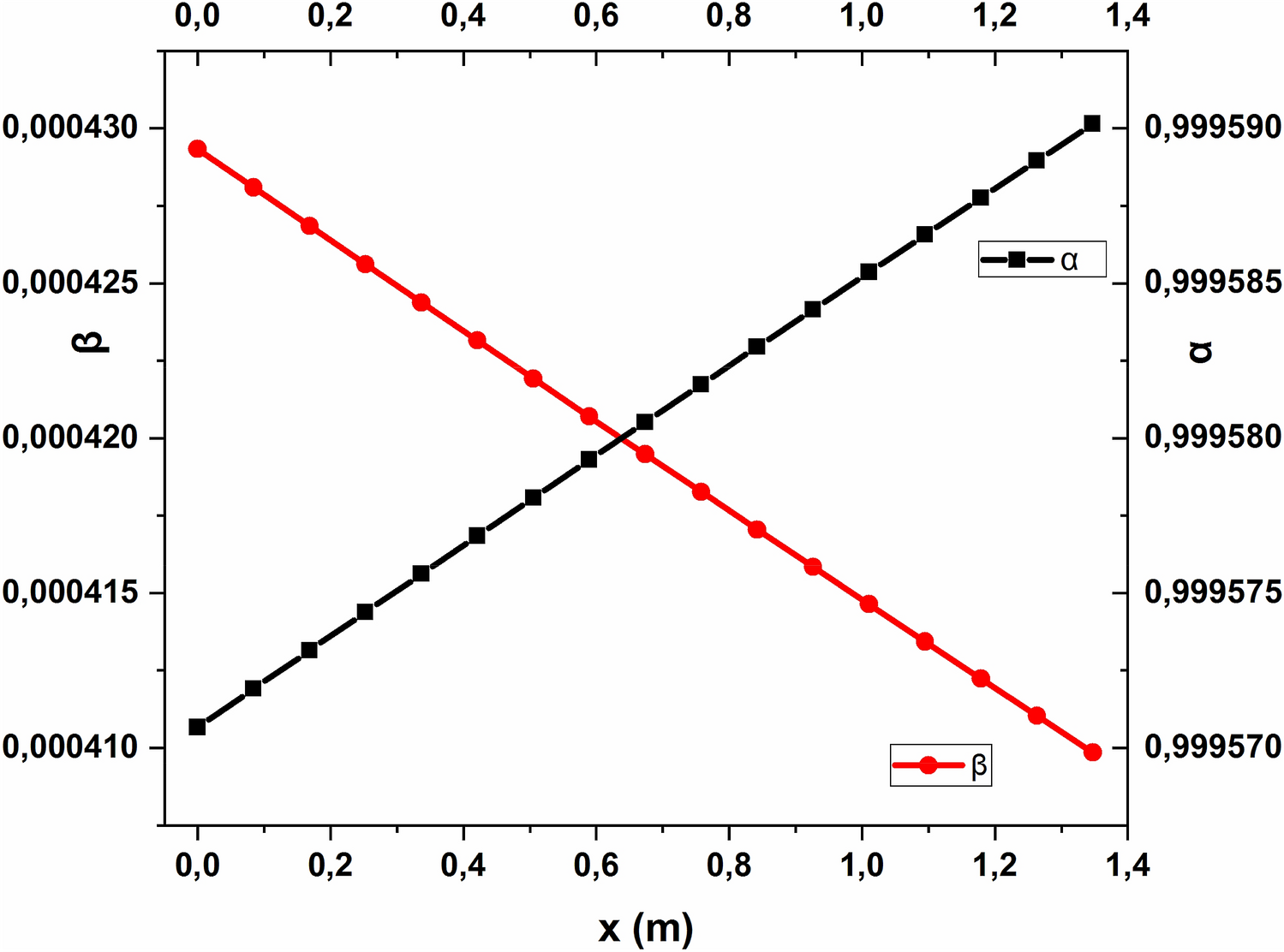
, there can be seen a small curvature of the graphs. This curvature increases with the liquid to gas ratio, with the throat length and with the throat diameter decrease which is discussed further in the paper.
Fig. 2
Variation of the dimensionless superficial velocity
a
in the liquid wall film
b
in the core of the flow (droplets);
L
/
G
= 0.027, where
L
stands for the liquid and
G
stands for the gas; droplet entrainment activated
Fig. 3
Scheme of the Venturi being analysed
Fig. 4
Pressure drop of the two-phe air–water flow in Venturi’s throat obtained through the use of the formula available in the literature (TP pressure drop, Eq. (
46
)) and author’s method (Flow core pressure drop, Eq. (
53
)); in both cases
L
/
G
= 0.027
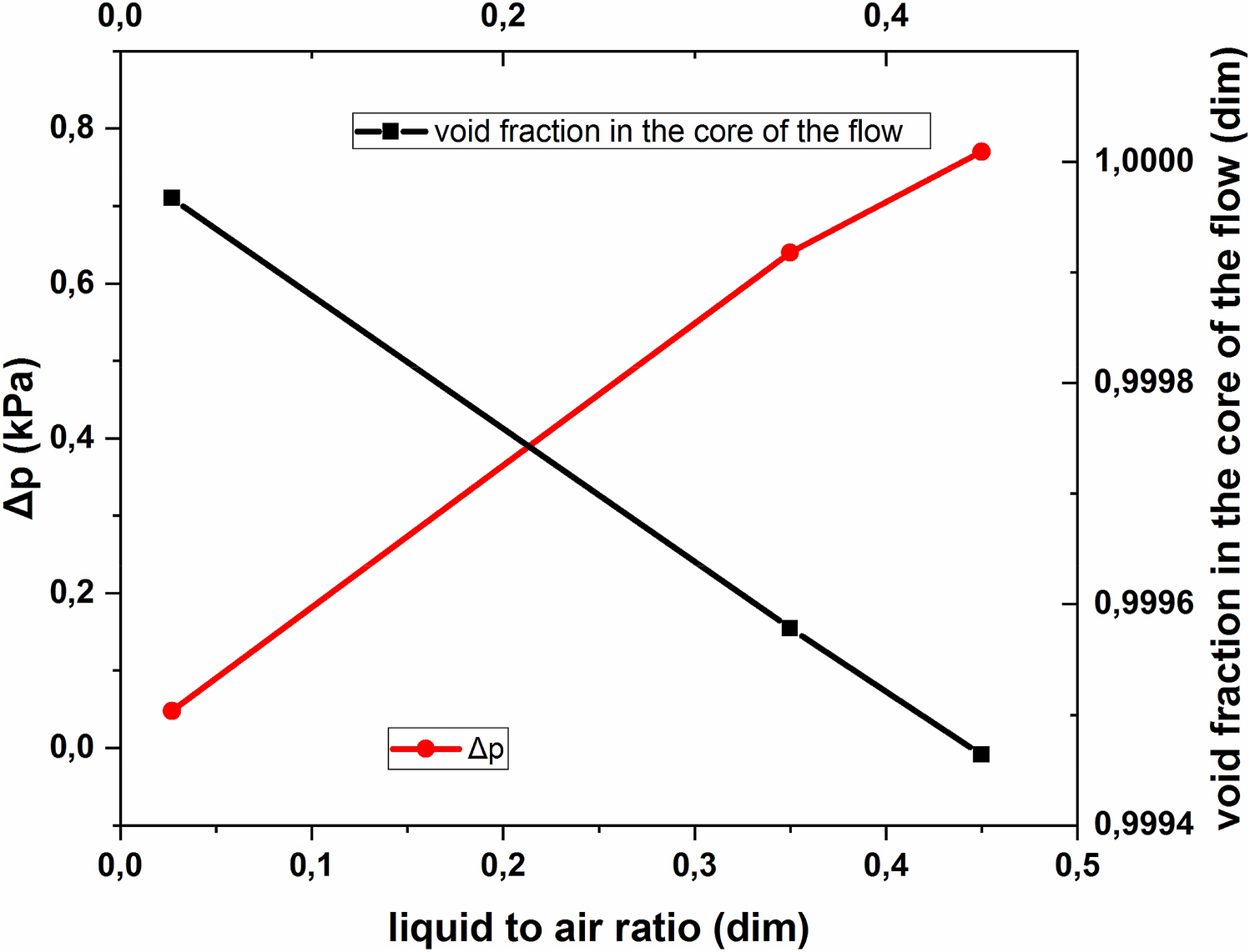
Analytical model validation
The model presented here concerns the liquid superficial velocity variation within the wall film and within the core of the two-phase flow along Venturi’s throat. According to the authors’ knowledge, there are no available data in the literature which could be used to verify the accuracy of the model predictions. Nevertheless, the works of Viswanathan [
8
] and Azzopardi et al. [
5
] confirm the correctness of the deposition-entrainment two-phase fluid flow modelling approach. Thus, the analytical model validation has been carried out indirectly, through the pressure gradient analysis and comparison to the experimental data published by Silva et al. [
17
] for a large-scale Venturi. Accordingly, in the analytical model calculations it was assumed that the two-phase air–water mixture flows at the rate of
m˙air
= 0.483 kg/s and
m˙w
= 0.013 kg/s on the inlet, respectively. Also, the diameter and the length of Venturi’s throat are equal
d
= 0.1225 m and
L
= 0.3 m, respectively (Fig.
3
). Liquid to gas ratio,
L/G
, in this case is equal 0.027. The experimental pressure drop in Venturi’s throat was equal to 114 Pa. The pressure drop was calculated using the following equation [
40
] (Fig.
4
):
Δp=2·G2ρν·d·Iz+pgrav+G2·x12·1ρνα1-1-x12·1ρl1-α1z=z1-x02·1ρνα0-1-x02·1ρl1-α0z=z0
where
pgrav
[Pa] is the term accounting for the gravitational head effects,
α
is the void fraction, subscripts: 0—Venturi’s throat inlet, 1—refers to a given distance in Venturi’s throat,
l
—corresponds to liquid (water),
ν
—corresponds to gas (air). All parameters used in Eq. (
46
) were obtained based on the analytical model calculations. There are three contributions influencing the pressure gradient in the two-phase flow. The first term on the right in Eq. (
46
) accounts for frictional head effect while the second one accounts for the gravitational head effect. In this particular case considered here,
pgrav
, amounts to zero because the horizontal throat with no slope is assumed (
Ω=0
). The third term describes the acceleration (or deceleration) of the flow.
In the first, frictional term,
Iz=∫z=z0z=z1fν·x2·ϕν2dz,
where
x
is the quality in the core of the flow and:
ϕν=1+C·X+X20.5
and
X
is the Lockhart-Martinelli parameter, defined as follows:
X=-2·fl·G2·1-x2ρl·d,
where
fl
is the friction factor for the liquid flowing alone in Venturi’s throat,
Ω
[
°]
is the slope angle of the channel. The above Eq. (
48
) is the two-phase multiplier Lockhart-Martinelli correlation [
40
]. Friction factors in Eq. (
47
) and in Eq. (
49
) are calculated from:
fν=B·Reν-n,fl=B·Rel-n,
where
fν
—friction factor for the vapour flowing alone in Venturi’s throat,
B=0.079
and
n=0.25
—for the turbulent flow or
B=16
and
n=1
—in the laminar flow [
40
]. The value of the constant
C
in Eq. (
53
) differs depending on the flow regime associated with the gas flow alone through Venturi’s throat. In the studies presented in the current paper only two flow regimes have been considered, namely a turbunt (gas)-turbulent (liquid) and turbulent (gas)-viscous (liquid) two-phase flows. Accordingly, the value of the parameter
C
used in the calculus was 20 or 12, respectively [
40
]. Following Butterworth, the general form of the void fraction correlations is introduced through the following equation [
40
]:
α=1+BB·1-xxn·ρνρln2·μlμνn3
and
α1
and
α0
were computed using Eq. (
52
). The parameters
BB
,
n
,
n2
and
n3
present in Eq. (
52
) can be found in [
40
], in Table 10.2. In the current studies, the following values of the parameters
BB=1
,
n=1
,
n2=1
,
n3=0
, corresponding to the homogenous two-phase flow regime, were used. The analytical two-phase fluid flow pressure drop was calculated using Eq. (
46
) which is common in the literature, e.g. [
40
]. In the current analytical studies Venturi’s throat is being considered. However, experiments, on the basis of which the model is being validated, have been carried out for the whole Venturi orifice. Thus, in the pressure drop calculus there must be included the confusor local pressure drop, resulting from the variation of the cross-section, to ensure the accordance of the theoretical model with the experiment. In the pressure drop calculus all needed parameters such as the friction factor for vapour flowing alone in the tube, the quality, the two-phase multiplier and the void fraction come from the analytical model results. The pressure drop was calculated in two ways. In the first one, the two-phase fluid flow parameters were used for the total flow in Venturi’s throat (Eq. (
46
)). In the second one, only the parameters of the core of the flow were used. The total pressure drop and the pressure drop in the flow core should be equal. Calculating the pressure drop based on the core-flow parameters requires the knowledge about the flow pattern in the core which results directly from the analytical model results presented in the paper. The core pressure drop was calculated with the use of the following equation (Fig.
4
):
Δp=2·Gcore2ρν·d·Iz+Gcore2·x12·1ρνφc,1-1-x12·1ρl1-φc,1z=z1-Gcore2·x02·1ρνφc,0-1-x02·1ρl1-φc,0z=z0,
where
φc=-ρlρν·uluν1-ρlρν·uluν-1x,
where subscripts
c, core
correspond to the parameters in the core of the flow,
φc
is the void fraction in the core of the flow. Equation (
54
) was derived for the purpose of the core void fraction estimation. If this parameter is known, the cross-section area of the mist flow can be calculated which results in estimation of the diameter needed in Eq. (
53
). After substituting the needed parameters mentioned just above, the core pressure drop can be estimated. It is worth to emphasise that the confusor local pressure drop was calculated based on the following formula:
Δpconfusor=ζconfusor·ρν·uν22,
where:
ζconfusor=0.1
[
43
];
Δpconfusor=68.57Pa
. The results obtained from the literature and based on Eq. (
46
), (
53
), including the confusor local pressure drop Eq. (
55
), are presented in Table
1
.
Table 1
Pressure drop of the two-phase fluid flow through the 0.3 m long Venturi throat
Source
Pressure drop [Pa]
Experimental result from the literature [17]
114.3
Calculated pressure drop for the total two-phase flow + Δpconfusor
117.47
Calculated pressure drop for the core two-phase flow + Δpconfusor
117.57
As a part of the research on the Venturi gas dynamics, the CFD analysis has been carried out for the single-phase air flow,
m˙air
= 0.483 kg/s, [
3
] and compared to the literature data [
17
].
Analytical model calculation results
The calculations have been carried out also for
m˙air
= 2 kg/s and
m˙w
= 0.7 kg/s and other values, listed in the Table
2
. The diameter of Venturi’s throat is the same as used in the previous chapter, that is
d
= 0.1225 m. The calculations results presented in this section have been carried out for two Venturi throat lengths, which are 0.3 m and 1.35 m. It can be seen in Fig.
5
how that the pressure drop varies with liquid (water) to gas (air) ratio in the throat of 0.3 m length. Additionally, it is shown there how the core void fraction varies with the
L/G
ratio. The character of the two graphs in Fig.
5
is rational as the void fraction in the core of the flow decreases with
L/G
ratio increase, and the overall pressure drop increases with
L/G
increase.
Table 2
L
/
G
ratio used for calculations
m˙lkgs
m˙νkgs
LG
0.013
0.483
0.027
0.7
2
0.35
1
2.2
0.45
Fig. 5
Variation of the pressure drop, Δ
p
and void fraction,
φc
, in the core of the flow at specific
LG=m˙lm˙ν
ratios listed in Table
2
; droplet entrainment activated
Droplet entrainment activated
Figures from Figs.
5
,
6
,
7
present the results for the case of the entrainment enabled. Obviously, as it was mentioned earlier in the text, the droplet deposition is present from the very beginning of the flow channel while the droplet entrainment starts to occur only if the condition defined by Eq. (
33
) is fulfilled.
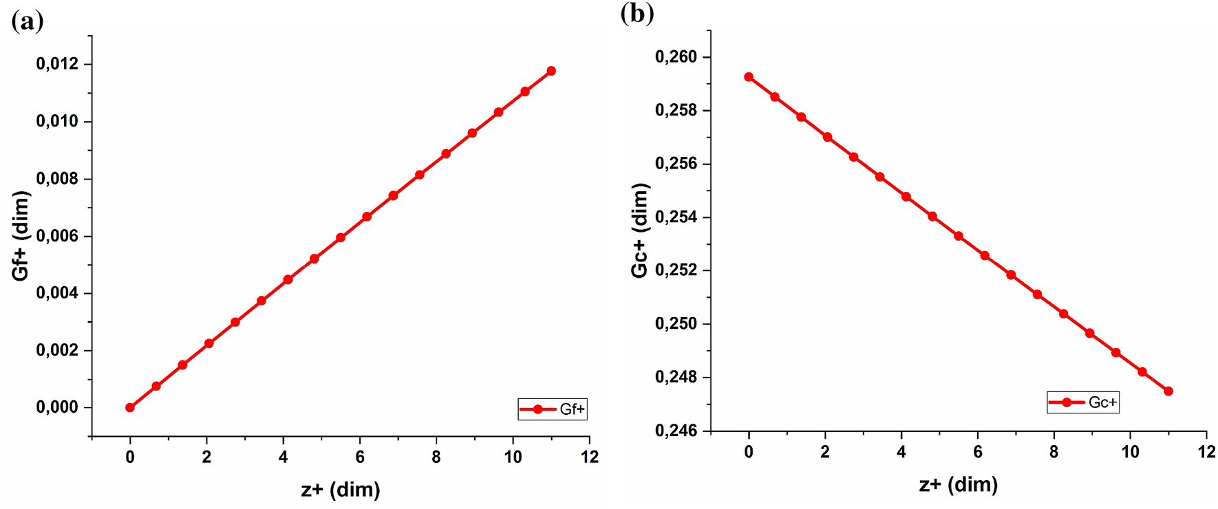
Fig. 6
Variation of the dimensionless
a
mass flux of the liquid wall film,
Gf+
,
b
liquid mass flux in the core of the flow,
Gc+
, defined by Eq. (
7
), versus the non-dimensional length of Venturi’s throat; droplet entrainment activated;
L
/
G
= 0.35
Fig. 7
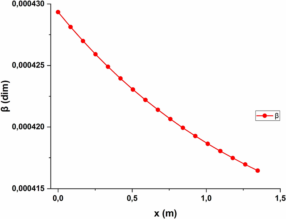
Variation of the liquid fraction (
β
= 1−α) in the two-phase flow in Venturi’s throat of total length 1.35 m; droplet entrainment activated;
L
/
G
= 0.35
Figure
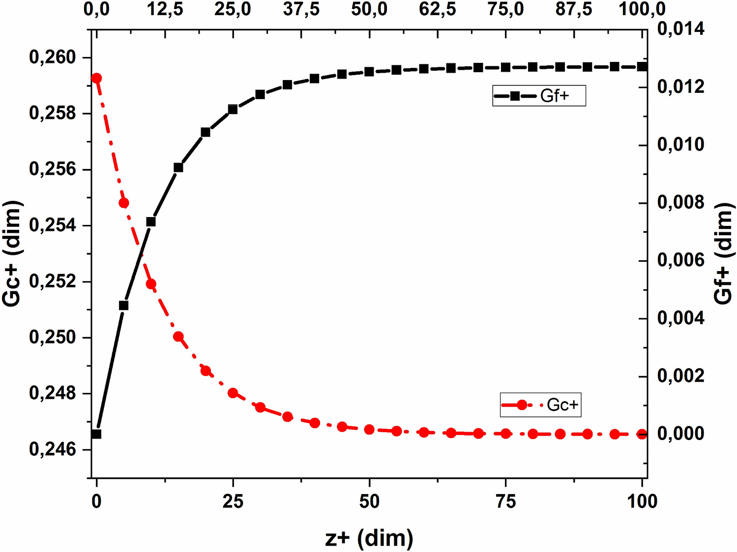
6
presents the variation of the water mass flux in the liquid wall film,
Gf+
, and in the core of the flow,
Gc+
, through 1.35 m Venturi throat. These characteristics have been obtained for
L/G
= 0.35. As it can be clearly seen the curvature of the lines is greater than in the case of the
L/G
= 0.027 shown in Fig.
2
.
The homogenous model of a two-phase flow, applied for the purpose of the current analytical research studies yields reasonably accurate results for limited range of the flow conditions (bubbly flow or mist flow). As it is shown in Fig.
1
, it is assumed that the mist flow exists in the core of the investigated two-phase flow domain (Table
3
). The void fraction, α, was calculated using Eq. (
52
). In Figs.
6
,
7
there are presented the results for the two-phase air–water flow, of the L/G ratio equal 0.35, with droplet entrainment and deposition activated as the critical mass flux was reached from the very beginning of Venturi’s throat.
Table 3
Liquid fraction
βc
in the core of the flow for selected Venturi throat diameters,
d
, and liquid to gas ratios
L
/
G
d [m] →
L/G↓
0.05
0.06
0.12
0.18
0.027
3.181•10–5
3.219•10–5
3.299•10–5
3.302•10–5
0.35
4.094•10–4
4.097•10–4
4.22•10–4
4.28•10–4
0.45
5.3075•10–4
5.3081•10–4
5.36•10–4
5.39•10–4
Droplet entrainment deactivated
Bearing on mind the validity of revealing the real influence of the droplet entrainment on both superficial water velocities,
Gf+
and
Gc+
, the case of the droplet entrainment neglecting is introduced in this paragraph (Figs.
8
,
9
). Therefore, figure exposed below (Fig.
8
) shows the similar characteristics as in the previous figure (Fig.
6
), however, the droplets entrainment is deactivated.
Fig. 8
Variation of the dimensionless superficial liquid velocity
a
in the liquid film at the wall,
Gf+
;
b
in the core of the flow,
Gc+
; droplet entrainment deactivated;
L
/
G
= 0.35; Venturi throat length 1.35 m
Fig. 9
Variation of the void (
α
) and liquid (
β
= 1−
α
) fraction in the two-phase flow through the total length of Venturi’s throat which is 1.35 m; droplet entrainment deactivated;
L
/
G
= 0.35
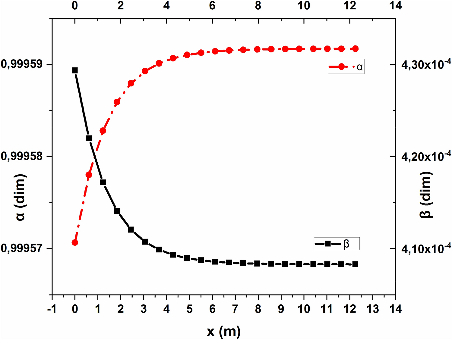
Analysis of Venturi’s throat geometrical parameters influence on the fluid flow pattern
The extreme channel length of 12.25 m was chosen intentionally to clearly visualise the overall
Gf+
and
Gc+
variation along such along channel. With the help of Fig.
10
a, remembering that
z+=zd
, one can determine the distance from the throat inlet where the steady state with respect to
Gf+
and
Gc+
is reached. Additionally, Fig.
11
can be used to find the critical length of Venturi’s throat at which a highest liquid fraction exists. Based on the current analytical model results it can be stated that, for the specific fluid flow parameters, assumed in the paper, the large-scale Venturi throat length could be less than 1 m. Large-scale Venturi nozzle can even reach the length of 0.65 m so, the results presented in the current paper are in a good accordance with the available literature data [
44
]. From Figs.
10
and
11
, it can be seen that the differential Eq. (
30
) is of a nonlinear character.
Fig. 10
Variation of the dimensionless liquid mass flux in the liquid film at the wall,
Gf+
, and in the core of the flow,
Gc+
, for the extremely long Venturi throat equal 12.25 m;
L
/
G
= 0.35
Fig. 11
Variation of the void (
α
) and liquid (
β
= 1−
α
) fraction in the two-phase flow through the total length of Venturi’s throat which is 12.25 m; droplet entrainment activated;
L
/
G
= 0.35
The volumetric liquid fraction variation in Venturi’s throat is presented in Fig.
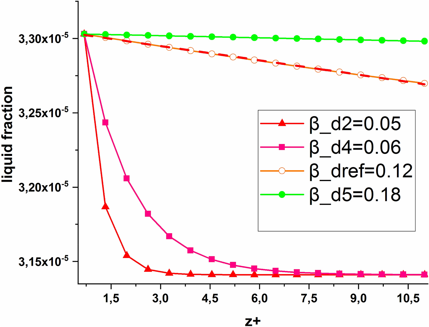
12
. As it can be seen, lowering the throat’s diameter strongly affects the liquid content, and it decreases with the diameter reduction. Thus, for the purpose of the syngas purification process large Venturi orifices should be used.
Fig. 12
Liquid fraction,
β
, variation in function of the non-dimensional throat length for selected values of the throat diameter (in metres);
L
/
G
= 0.027
Based on Eq. (
54
), the mean core liquid fraction was estimated from the relationship
βc=1-φc
It was found that
βc
varies significantly with L/G ratio and slightly with the throat diameter
d
. This parameter plays a significant role in the syngas purification process as it gives the information about a droplet content in the in the core of the flow. Each droplet may collect particular amount of solid particles. Estimation of a droplet content in the core of the flow is therefore necessary in the estimation of dust particles collection efficiency. In general, the greater
βc
, the higher efficiency is being reached.
Conclusions
Current investigations based on a novel analytical model, presented in the paper, have led to the estimation of the pressure drop and liquid fraction in the flow, along the Venturi throat. The introduced model allows for the pressure drop calculation with the use of the core-flow parameters. Additionally, the model allows for determining the mass flux of the liquid film at the channel walls and the mass flow rate of the liquid in the core of the flow. Present model takes into consideration two important phenomena existing in the two-phase flow. Namely, the deposition of the liquid droplets within the liquid wall film and the entrainment of the drops from the wall film to the core of the two-phase fluid flow. The innovative concept presented in the paper leads to set of equations which is solved analytically in the paper. The proposed model enables prediction of the throat length at which there occur both the deposition and entrainment of the droplets. Moreover, the wall film mass flux variation in the channel is being estimated. The distance at which there occur the droplet entrainment is an individual parameter which depends on the liquid and gas inlet mass flow rates and the channel diameter. The analytical studies on the two-phase fluid flow with droplets deposition and entrainment, presented in the paper, have led to the conclusion that the liquid mass flux variation in the film and in the core of the flow is nonlinear. The results also show that neglecting the droplets entrainment leads to the linearization of the mentioned characteristics (Figs.
8
,
9
.) In the paper, the core-flow parameters were determined and can be used in the pressure drop estimation with a satisfactory accuracy. Investigations on the influence of the throat length and diameter variation on the studied two-phase flow have led to the statement that large diameter (Fig.
12
) and throat length less than one metre (Fig.
11
) may lead to higher cleaning efficiency. Additionally, the liquid fraction in the core-flow was estimated which is essential when it comes to the cleaning efficiency estimation. The analytical model gives reasonable results, and it is planned to be further expanded by adding confusor and diffuser to the Venturi cylindrical throat which was analysed in the current paper. Moreover, based on the presented analytical considerations, dust collection efficiency is planned to be estimated in the future work.
Acknowledgements
The work was founded by the statutory budget of the Institute of Fluid Flow Machinery of Polish Academy of Sciences. The work on the supplement data was founded by the National Science Centre, Poland, No. 2019/03/X/ST8/00608.
Publisher's Note
Springer Nature remains neutral with regard to jurisdictional claims in published maps and institutional affiliations.
References
Śliwińska (2010) Evaluation of the impact of the carbon dioxide capture technologies on the environment in the electrical energy generation process (pp. 90-96)
Unknown ()
Dolna (2019) Venturi scrubbers – literature review and CFD analysis 4(143) (pp. 26-32)
Woolcock and Brown (2013) A review of cleaning technologies for biomass-derived syngas (pp. 54-84) 10.1016/j.biombioe.2013.02.036
Unknown ()
Gonçalves et al. (2004) Atomization of liquids in a Pease-Anthony Venturi scrubber, Part II. Droplet Separation (pp. 147-157) 10.1016/j.jhazmat.2004.08.030
Allen (1996) Designing for pressure drop in Venturi scrubbers: the importance of dry pressure drop (pp. 203-211) 10.1016/0923-0467(95)03044-1
Viswanathan (1998) Examination of liquid film characteristics in the prediction of pressure drop in a Venturi scrubber 53(17) (pp. 3161-3175) 10.1016/S0009-2509(98)00123-7
Gamisans et al. (2002) The hydrodynamics of ejector-venturi scrubbers and their modelling by annular flow/boundary layer model (pp. 2707-2718) 10.1016/S0009-2509(02)00171-9
Xavier et al. (2002) Gas pollutants removal in a single and two stage ejector venturi scrubber (pp. 251-266)
Goncalves et al. (2003) Atomization of liquid in a Pease-Anthony Venturi scrubber Part I. Jet dynamics 97(Part B) (pp. 267-297) 10.1016/S0304-3894(02)00266-2
Goncalves et al. (2004) Atomization of liquid in a Pease-Anthony Venturi scrubber Part II. Droplet dispersion 116(Part B) (pp. 147-157) 10.1016/j.jhazmat.2004.08.030
Leith et al. (1985) Venturi scrubbers: pressure loss and regain (pp. 239-243) 10.1080/02786828508959052
Hesketh (1974) Fine particle collection efficiency related to pressure drop, scrubbant and particle properties and contact mechanism 24(10) (pp. 939-942) 10.1080/00022470.1974.10469992
Boll (1973) Particle collection and pressure drop in venturi scrubber 12(1) (pp. 40-49) 10.1021/i160045a008
Azzopardi et al. (1991) An improved model for the pressure drop in venturi scrubbers (pp. 55-64)
Azzopardi (1992) Gas-liquid flows in cylindrical Venturi scrubbers: boundary layer separation in diffuser section10.1016/0300-9467(92)85025-5
Azzopardi (1993) Liquid distribution in Venturi scrubbers: the importance of liquid films on the channel walls (pp. 2807-2813) 10.1016/0009-2509(93)80191-R
Viswanathan et al. (1985) Annular flow pressure drop model for Pease-Anthony-type Venturi scrubbers (pp. 1947-1958) 10.1002/aic.690311204
Unknown ()
Unknown ()
Sedler and Mikielewicz (1981) A simplified method of the boiling crisis (pp. 431-438) 10.1016/0017-9310(81)90050-8
Pak and Chang (2006) Performance estimation of a Venturi scrubber using a computational model for capturing dust particles with liquid spray (pp. 560-573) 10.1016/j.jhazmat.2006.05.105
Unknown ()
Hewitt and Hall-Taylor (1970) Pergamon Press
Liu et al. (2019) The study of critical heat flux in upflow boiling vertical round tube under high pressure10.1155/2019/3695685
Unknown ()
Friedlander and Johnstone (1957) Deposition of suspended particles from turbulent gas stream 49(7) (pp. 1151-1156) 10.1021/ie50571a039
Flagan and Seinfeld (1988) California Institute of Technology, Prentice Hall
Carey (2008) Taylor & Francis Group LLC
Unknown ()
Dolna and Mikielewicz (2019) Separation of droplets in the field of a boundary layer 92(5) (pp. 1202-1206) 10.1007/s10891-019-02034-1
Mikielewicz et al. (2008) Modelling of the dryout process in an annular flow 39(7) (pp. 587-596) 10.1615/HeatTransRes.v39.i7.30
Goel et al. (2019) Numerical simulation of injection characteristics, hydrodynamics and absorption of iodine vapour in a venturi scrubber operating in self-priming mode (pp. 360-367) 10.1016/j.nucengdes.2018.11.020