Faculty of Electrical and Computer Engineering, Shahid Beheshti University, Tehran, IR
Faculty of Engineering and Technology, Imam Khomeini International University, Qazvin, IR
School of Electrical, Electronics and Robotics Engineering, Shahrood University of Technology, Shahrood, IR
Mazandaran Electric Distribution Co., Mazandaran, IR
Abstract
Optimal reconfiguration and capacitor placement are used to reduce power losses and keep the voltage within its allowable interval in power distribution systems considering voltage, current, and radial condition constraints. It is needed to solve two nonlinear discrete optimization problems simultaneously, so an intelligent algorithm is used to reach an optimum solution for network power losses. An effective method and a new optimization algorithm using “improved binary PSO” is presented and discussed to minimize power losses in distribution network by simultaneous networking of reconfiguration and capacitor placement. The proposed model uses binary strings which represent the state of the network switches and capacitors. The algorithm is applied and tested on 16- and 33-bus IEEE test systems to find the optimum configuration of the network with regard to power losses. Five different cases are considered and the effectiveness of the proposed technique is also demonstrated with improvements in power loss reduction compared to other previously researched methods, through MATLAB under steady-state conditions.
Introduction
Power distribution network consists of a group of radial feeders which can be connected together by several tie-switches and tie-lines. The power loss reduction in the network is a major concern of electric distribution utilities. Among conventional methods, optimal reconfiguration and capacitor placement are two effective methods which can be applied on the network.
The optimization methods have been used to find the optimal location and size of different devices such as capacitors, FACTS, Distributed generations, etc. in power distribution systems [
1
–
3
]. In this paper the optimization methods are used for optimal reconfiguration and capacitor allocation in power systems.
Feeder reconfiguration is the process of changing the distribution network topology by changing the status of its switches. There are two kinds of switches based on their open or close conditions: normally open (NO) and normally close (NC). Normally open switches are considered as tie switches in the network. During reconfiguration process, the status of these switches will be changed optimally based on the proposed objective function. Opening and closing of these switches can change the amount of power losses.
On the other hand, capacitors are mostly used for reactive power compensation in distribution networks. They are also used for power loss reduction and improvement of voltage profiles. The advantages of this kind of compensation depend on how and where to place the capacitors in the network. In recent years, according to proper results of optimal capacitor placement and optimal distribution network reconfiguration for power losses reduction, the idea of using these two methods simultaneously has been considered to maximize the amount of power loss reduction. The combination of these approaches makes the optimization process more complex.
Optimal capacitor placement and feeder reconfiguration have been investigated in many papers separately and various approaches have been used with different objective functions to model the network and optimize the problem solution.
In [
4
], the branch and bound heuristic method has been used to solve the reconfiguration problem with minimum power losses. In this method, all network switches become closed and will be opened one by one to obtain a new radial configuration. In [
5
], the power loss reduction and load balancing reconfiguration problem is formulated as an integer programming method. The branch exchange heuristic method is proposed in [
6
]. In this method, power losses reduction is obtained by closing a switch and opening another one. In [
7
], an algorithm has been proposed to obtain switch pattern as a function of time. A load flow method based on a heuristic algorithm has been introduced in [
8
] to determine a configuration with minimal power losses. An implementation using a genetic algorithm (GA) has been proposed in [
9
]. An improved genetic algorithm based on fuzzy multi-objective approach has been suggested in [
10
] to solve the problem. In [
11
], a method based on binary particle swarm optimization (BPSO) algorithm is presented to balance network loads. In [
12
], the authors have used ant colony search algorithm (ACSA) to solve the reconfiguration problem. Moreover, they have performed a comparison which shows better results for ACSA compared to genetic algorithm (GA) and simulated annealing (SA). A solution procedure employing SA is proposed in [
13
] and [
14
] to search for an acceptable non-inferior solution. In [
15
], the network reconfiguration problem has been solved by a harmony search algorithm (HSA) and an optimal switching combination in the network is obtained which results in minimum power loss.
Many investigations have also been performed to solve the optimal capacitor placement problem. Grainger and Lee [
16
–
18
] formulated the problem using a non-linear programming model and solved it by simple iterative procedures based on gradient search. In [
19
] and [
20
], the capacitor placement problem is modeled as a mixed integer non-linear programming problem and is solved using a decomposition method and a power flow algorithm. In [
21
], Tabu search (TS) algorithm is used and a sensitivity analysis is performed to reduce the search space. It is shown that TS has a better performance compared to SA. In [
22
], the placement problem is solved together with finding the amount of proper capacitors. An approach using GA and a new type of sensitivity analysis method is used. In [
23
], the implementation of integrated evolutionary algorithms is investigated for solving the capacitor placement optimization problem with reduced annual operating cost. Differential evolution and pattern search (DE-PS) are used as meta-heuristic optimization tools to solve optimal capacitor placement problem.
Some papers considered these two problems simultaneously. In [
24
], optimal capacitor placement and reconfiguration problem is considered as two consecutive stages and the branch exchange method is used for reconfiguration process. In [
25
], SA is used to solve optimal capacitor placement and reconfiguration. The amounts of capacitances are determined by a discrete optimization algorithm. Simultaneous solution of these two problems has been approached with the objective of power loss minimization in [
26
] and the ACSA has been compared to SA and GA and its superior results have been presented. In [
27
], a modified PSO algorithm is used to solve the optimal capacitor placement and reconfiguration problems. The proposed objective function contains power loss minimization and cost reduction in specific periods of time. In [
28
], a heuristic algorithm is used for reliability evaluation considering protection schemes and isolation points in the distribution network. The problems are solved by Harmony Search Algorithm. In [
29
], a deterministic approach for network reconfiguration and a heuristic technique for optimal capacitor placement for power loss reduction and voltage profile improvement in distribution networks are presented. A minimum spanning tree (MST) algorithm is utilized to determine the configuration of minimum power losses along with a GA for optimal capacitor placement.
All previous reports, regardless of their objective function, are looking for the most optimum or a global optimum solution. Meanwhile, each proposed method tries to reach a more optimal or near optimal solution compared to previous works.
In this paper, some planning issues for the priority of reconfiguration and capacitor placement problems in power distribution networks are investigated based on a new improved binary PSO (IBPSO) algorithm. The algorithm is used to solve the simultaneous reconfiguration and optimal capacitor placement problem. The proposed method employs a different structure for the optimization algorithm (by using logical operators AND, OR, and XOR). A near-global optimum feeder reconfiguration and capacitor setting is obtained which shows the best results among other previous similar works. The proposed IBPSO algorithm is compared with other intelligent algorithms [SA, GA, ant colony optimization (ACO), and ACSA] and its better performance is presented. Then the priority of reconfiguration and capacitor placement cases are presented in the “
Discussion
” section.
Problem formulation
The objective is to minimize the network power losses considering constraints under a specified load pattern. The mathematical model of the problem can be expressed as follows [
26
]:
where
is the total real power loss of the network. The parameters
and
are penalty constants,
is squared sum of the violated voltage constraints, and
is squared sum of the violated current constraints [
26
].
is used to apply constraints on the objective function. The voltage magnitude at each bus must remain within its allowable interval. Besides, the current of each branch must satisfy the branch current limitations. These intervals are expressed as follows:
where
is the voltage magnitude of bus I and
and
are minimum and maximum allowable voltages, respectively, which are considered as
and
.
is the current magnitude and
is the maximum current limit of the branch
i
. So, the penalty constants are determined as follows:
and/or
equal to 0, if the associated voltage/current constraint is not violated.
A significant value is given to
and/or
when the associated voltage/current constraint is violated; this makes the objective function move away from the undesirable solution [
26
]. This significant value is considered equal to the amount of objective function before the optimization process (in this study, the initial power loss of the test network) multiplied by a large number (for example 10
4
). This process is performed automatically by the developed program.
To obtain the network’s power losses and voltage drops, a load flow calculation should be performed during the optimization process. Conventional methods of load flow are Gauss–Seidel and Newton–Rafson which lead to unreliable solutions in radial distribution networks due to the radial structure and the high
R
/
X
ratio. Therefore, a backward–forward load flow method (BF-load flow) is used in this paper. Other previous reports chose the same load flow method, too [
27
,
33
]. The BF-load flow method is fully presented in [
32
] which is explained briefly in the following section.
Backward–forward (BF) load flow method
A BF-load flow has been used to evaluate the objective function of the problem. In BF-load flow, the first step is to introduce the topology of distribution network to the computer program as meaningful matrices using graph theory [
32
]. Then the main process will begin as follows:
The vector (
) containing the voltages of the nodes is defined. At first, we assume that all the elements of the vector are equal to 1 pu (or 1.05 pu) with zero angle.
The currents of nodes (
) is calculated by the following equation:
where
are current, apparent power and voltage of the load in the node #
i
, respectively.
The current of the last node is the current of the last branch. So the currents of network branches (
) are calculated starting from the last node to the first one by using Kirchhoff’s current law (KCL) (Backward sweep).
f
is the number of network branches.
The voltage drop is calculated by the equation
LU
=
ZJ
.
Z
is the impedance and
is the voltage drop of each branch.
The voltage of reference node is equal to 1 or 1.05 pu. The voltage of the next node is calculated by subtracting the corresponding voltage drop from the voltage of previous node (forward sweep) and
will be updated.
The procedure is restarted from step 2 with recently calculated
. The convergence condition is
where
K
is the iteration number and
is the calculation error (precision).
Improved binary particle swarm optimization
Overview
Binary particle swarm optimization (BPSO) algorithms were introduced by Kennedy and Eberhart in 1997. In a standard BPSO algorithm, real numbers are used in the optimization process. The proposed algorithm uses a method similar to the standard basic PSO and a random method produces a new swarm. The particles’ velocities are calculated using the established relationships in the standard mode. The new amounts of particles’ position are 0 or 1 which is retrieved from the comparison of calculated velocity with a random number. This method has several disadvantages. The information of particles obtained from previous iterations is not used in the next iteration and the positions of particles are updated almost randomly which leads to inappropriate results. Therefore, “improved binary particle swarm optimization” (IBPSO) algorithm has been introduced in [
30
].
Improved binary particle swarm optimization
In IBPSO method, the information of every particle in iterations is used to determine new particles. Thus, if each particle contains
d
dimensions (variables), in the iteration
k
+ 1 we will have
where “
”, “
” and “+” denote “XOR”, “AND”, and “OR” operators, respectively.
w1
and
w2
are inertia weight factors which are random binary strings.
is the
d
th dimension velocity of particle
i
at iteration
k
+ 1.
and
are the
d
th dimension of the personal best position of particle
i
until iteration
k
and the
d
th dimension of the best position of all particles in the swarm at iteration
k
, respectively. The new position of each particle can be updated by Eq. (
7
):
where
is the
d
th dimension position of particle
i
at iteration
k
[
30
]. The problem will be formulated based on this optimization process.
Implementation of the optimization algorithm
Implementation steps of the IBPSO algorithm to solve the optimal reconfiguration and capacitor placement problem are as follows:
The inputs of the procedure are:
w1
and
w2
, swarm size (
P
), objective function and maximum iterations.
To start the procedure, the initial swarm is generated containing random binary strings. Each particle of the swarm indicates the ON/OFF condition of switches, the condition of capacitor installation on each node, and the size of located capacitors. Thus, if the number of decision variables (dimension of the search space) is considered
N
, then the initial swarm will be a
P
×
N
matrix as follows:
Each row of
S
is a particle flying in the search space. A special coding process is used to build the matrix
S
.
As mentioned above, each particle consists of three parts: the ON/OFF condition of switches, the condition of capacitor installation on each node, and the size of located capacitors which are denoted by three variables:
switch_condition
,
cap_condition
, and
cap_size
, respectively.
In the
switch_condition
, the length of binary string is
r1
+
r2
where
r1
is the number of NC switches and
r2
is the number of tie-switches. Every branch is considered as a potential switch which can be open or closed. Open and closed switches are shown by 0 and 1, respectively.
In the
cap_condition
, the number of required bits (
r3
) equals to the number of system nodes. The installation of a capacitor on a node is shown by 1. If there is no capacitor on a node, the corresponding bit will be 0 in the string.
In the third part of the string, the
cap_size
, the length of the string equals to the product of the number of nodes (
r3
) and the number of capacitors’ encoding bits. For example, (001)
2
to (110)
2
is the binary number of capacitor types 1–6 for 6 different capacitances and the number of bits is 3. Thus, in a 16-node network, the
cap_size
will be a 48-bit string.
Finally,
cap_size
and
cap_condition
bits are multiplied together to determine the location and the size of the capacitors. Figure
1
shows a string of a typical particle.
Fig. 1
A string of random typical particle
Network radial condition is verified in each iteration. This function checks two main conditions: (1) the network must contain no loops; (2) all of the nodes must be energized (connected the supply). So the program considers the radial network as a tree of the initial graph and the above-mentioned condition are verified as the network remains a tree in different states. In other words, a network remains radial if the graph of the network remains a tree. If it is confirmed, then the load flow will be run on the new generated network and the nodes’ voltages and the branches currents will be recalculated. In this step, the constraints are also checked and applied to the objective function according to Eq. (
1
).
pbest and gbest are calculated and updated in each iteration. They are the strings which result in the least amount of the objective function. The program will continue to run to reach the maximum predefined number of iterations. The last calculated gbest is the best status of the network and its corresponding power loss is the optimum solution.
Figure
2
shows the flowchart of the proposed process.
Fig. 2
The flowchart of the proposed algorithm
Simulation results and discussion
Optimal reconfiguration and capacitor placement is performed using the proposed algorithm on two IEEE test systems. The systems are well-known benchmark systems which are selected to compare the obtained results to previously reported optimization attempts on the same networks. The algorithm has been implemented in MATLAB R2010.
Six types of capacitors 300, 600, 900, 1,200, 1,500, and 1,800 KVAR are used in capacitor placement. The capacitors are numbered from 1 to 6, respectively, and 0 denotes a node without any capacitor. The selected ranges of capacitors are the same as previous reports for comparison purposes [
26
,
27
]. Their binary equivalent is defined according to Table
1
.
Table 1
Binary equivalent of capacitors
Types of capacitors
Binary equivalent
0: no capacitor
(0 0 0)
1: 300 KVAR capacitor
(0 0 1)
2: 600 KVAR capacitor
(0 1 0)
3: 900 KVAR capacitor
(0 1 1)
4: 1,200 KVAR capacitor
(1 0 0)
5: 1,500 KVAR capacitor
(1 0 1)
6: 1,800 KVAR capacitor
(1 1 0)
16-bus system
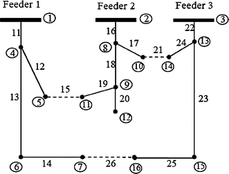
The first study is performed on a 16-bus system with 3 feeders which is shown in Fig.
3
. Thirteen continuous lines indicate NC switches, while NO switches (tie-switches) 15, 21, and 26 are represented by dotted lines. The initial network power loss is 511.44 kW [
6
].
Fig. 3
16-bus distribution system
The results of the optimization on a 16-bus test system are shown in Table
2
. Power loss has been reduced 12.38 % compared to the initial condition of the network. Five capacitors (1,500, 900, 1,800, 900, and 900 KVAR) are used in the optimal case which are placed on buses 4, 7, 8, 9, and 13, respectively.
Table 2
Results of optimal reconfiguration and capacitor placement in 16-bus system
Original configuration of system
After reconfiguration and capacitor placement
Tie-switches
15, 21, 26
19, 7, 26
Power loss (KW)
511.4
448.07
Maximum voltage (pu)
Umax = 1 (buses 1, 2, 3)
Umax = 1 (buses 1, 2, 3)
Minimum voltage (pu)
Umin = 0.9693 (buses 12)
Umin = 0.9757 (buses 12)
Power loss reduction (%)
–
12.38
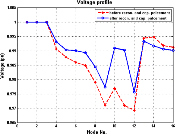
Figure
4
shows the voltage profiles before and after optimal reconfiguration and capacitor placement. The voltage profile is obviously improved after the optimization.
Fig. 4
Comparison of voltage profile before and after optimal reconfiguration and capacitor placement in 16-bus test system (
dashed line
before optimization,
solid line
after optimization)
33-bus system
The other case is Baran and Wu [
19
,
20
] test system shown in Fig.
5
. The normally open switches (s33, s34, s35, s36, s37) are represented by doted lines and normally closed ones (s1–s32) are illustrated by solid lines. The initial power loss is 202.68 kW [
31
].
The results of the improved binary PSO algorithm on 33-bus test network are shown in Table
3
. Power loss reaches to 93.061 KW which shows a 54.08 % reduction. Five capacitors (600, 300, 300, 600, and 300 KVAR) are used in the optimal case which are placed on buses 6, 11, 24, 29, and 32, respectively.
Table 3
Results of optimal reconfiguration and capacitor in 33-bus system
Original configuration of system
After reconfiguration and capacitor placement
Tie-switches
33, 34, 35, 36, 37
7, 9, 14, 32, 37
Power losses (KW)
202.68
93.061
Maximum voltage (pu)
Umax = 1 (buses 0)
Umax = 1 (buses 0)
Minimum voltage (pu)
Umin = 0.9131
Umin = 0.9587
Power loss reduction (%)
–
54.08
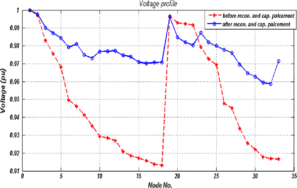
Figure
6
shows the voltage profiles before and after the optimal reconfiguration and capacitor placement. Again, it is observed that the voltage profile is improved after applying the optimization.
Fig. 6
Comparison of voltage profile before and after optimal reconfiguration and capacitor placement in 33-bus test system (
dashed line
before optimization,
solid line
after optimization)
Discussion
Tables
4
and
5
compare five different cases which employ optimal reconfiguration and capacitor placement separately and simultaneously. The following cases are considered:
Table 4
comparison of different cases for optimal reconfiguration and capacitor placement in 16-bus system
Parameters
Original case
Case 1
Case 2
Case 3
Case 4
Case 5
Tie-switches
15
21
26
17
19
26
15
21
26
17
19
26
17
19
26
17
19
26
Maximum voltage (pu)
1
1
1
1
1
1
Minimum voltage (pu)
0.9693
0.9716
0.·973
0.9763
0.9736
0.9757
Power losses (KW)
511.44
466.13
487.2
448.7
453.10
448.07
Nodes no.
Placed capacitors (KVAR)
1
–
–
–
–
–
–
2
–
–
–
–
–
–
3
–
–
–
–
–
–
4
–
–
1,800
1,200
1,800
1,500
5
–
–
300
–
300
–
6
–
–
–
–
–
–
7
–
–
900
900
900
900
8
–
–
1,800
1,800
1,800
1,800
9
–
–
–
1,200
–
900
10
–
–
1,500
–
1,500
–
11
–
–
–
–
–
–
12
–
–
–
–
–
–
13
–
–
–
–
–
900
14
–
–
–
–
–
–
15
–
–
–
–
–
–
16
–
–
–
300
–
–
Table 5
Comparison of different cases for optimal reconfiguration and capacitor placement in 33-bus system
Parameters
Original case
Case 1
Case 2
Case 3
Case 4
Case 5
Tie-switches
33, 34, 35, 36, 37
7, 9, 14, 32, 37
33, 34, 35, 36, 37
7, 9, 14, 32, 37
7, 10, 34, 36, 37
7, 9, 14, 32, 37
Maximum voltage (pu)
1
1
1
1
1
1
Minimum voltage (pu)
0.9131
0.9378
0.9389
0.9612
0.9658
0.9585
Power losses (KW)
202.68
139.55
134.2
94.26
95.91
93.06
Nodes no.
Placed capacitors (KVAR)
1
–
–
900
–
900
–
2
–
–
–
–
–
–
3
–
–
300
–
300
–
4
–
–
–
1,200
–
–
5
–
–
–
–
–
–
6
–
–
–
–
–
–
7
–
–
–
900
–
600
8
–
–
–
1,800
–
–
9
–
–
–
1,200
–
–
10
–
–
–
–
–
–
11
–
–
–
–
–
–
12
–
–
–
–
–
300
13
–
–
–
–
–
–
14
–
–
300
–
300
–
15
–
–
–
–
–
–
16
–
–
–
300
–
–
17
–
–
–
–
–
–
18
–
–
–
–
–
–
19
–
–
–
–
–
–
20
–
–
–
–
–
–
21
–
–
–
–
–
–
22
–
–
300
–
300
–
23
–
–
–
–
–
–
24
–
–
300
–
300
–
25
–
–
–
–
–
300
26
–
–
–
–
–
–
27
–
–
–
–
–
–
28
–
–
–
–
–
–
29
–
–
–
–
–
–
30
–
–
600
–
600
600
31
–
–
600
–
600
–
32
–
–
–
–
–
–
33
–
–
–
–
–
300
Case #1. Only network reconfiguration;
Case #2. Only capacitor placement;
Case #3. First, network reconfiguration and then capacitor placement;
Case #4. First, capacitor placement and then network reconfiguration;
Case #5. Network reconfiguration and optimal capacitor placement, simultaneously;
Case #5 (optimal reconfiguration and capacitor placement simultaneously) leads to the most optimum network condition. The comparison is mainly performed between the cases 3, 4, and 5 in which both reconfiguration and capacitor placements are carried out. However, there are differences between priorities of these cases. According to the amount of power loss reduction resulting from the simulation, optimization cases are categorized in distribution networks as follows:
Case #5 (Optimal network reconfiguration and capacitor placement simultaneously);
Case #3 (First, network reconfiguration and then capacitor placement);
Case #4 (First, capacitor placement and then network reconfiguration);
The other conclusion is obtained by comparing the results of IBPSO algorithm to other intelligent methods that were previously applied in different references with similar conditions (constant power loads and the consideration of voltage and current constraints) in 16-bus system. Table
6
shows this comparison. It is concluded that the proposed algorithm in this paper leads to a better result than other previously proposed methods.
Table 6
Comparison of intelligent algorithms to solve optimal reconfiguration and capacitor placement problem in 16-bus system
Used intelligent algorithm
Power losses
IBPSO
448.07
GA [26]
448.2
SA [26]
448.3
ACSA [26]
448.1
ACO [33]
450
The comparison is also done in the 33-bus case. Table
7
compares the result of applied methods to previous studies in a similar condition on the 33-bus system. Significant improvement is obtained using the proposed algorithm compared to previous reports of other researchers.
Table 7
Comparison of intelligent algorithms to solve optimal reconfiguration and capacitor placement problem in 33-bus system
Used intelligent algorithm
Power losses
IBPSO
93.061
ACO [33]
95.79
Environmental benefits
One of the most important benefits of power and energy loss reduction is its positive environmental impacts. This subject is so important especially in countries like Iran where a large amount of power generation is from fossil fuel power plants.
In such countries, the serious consequence of increase in conventional power generation is the increase of CO
2
, SO
x
and NO
x
emissions. Since the power and energy losses reduce power plants’ useful generation, any effective method to decrease the losses is so important. On the other hand, power distribution networks are responsible for a significant percentage of power and energy losses.
The proposed method in this paper is able to decrease the amount of losses in power distribution networks, considerably. In conventional power plants, the generated emissions are equal to 720 kg CO
2
, 0.1 kg NO
x
, and 0.0036 kg SO
2
per MWh. By using the proposed algorithm, the amount of emission can be decreased, consequently [
34
].
The amount of annual energy loss reduction can be calculated as follows:
where
LF
is the loss factor. In this study, all loads are considered to be residential with
LF
equals to 0.3.
Table
8
shows the amount of emission reduction due to the reduction of energy losses in the test networks.
Table 8
The amount of emission reduction due to the reduction of energy losses in the test networks by applying optimal reconfiguration and optimal capacitor placement simultaneously
Annual energy losses (MWh)
CO2 reduction (kg)
SO2 reduction (kg)
NOx reduction (kg)
16-bus test network
166.431
119,830.32
0.6
16.643
33-bus test network
288.078
207,416.16
1.037
28.807
It is clear from Table
8
that the amount of CO
2
, SO
2
, and NO
x
emissions are significantly decreased.
Conclusion
In this paper, simultaneous optimal reconfiguration and capacitor placement problem is solved in distribution networks to achieve the minimum power loss in the network. In the optimization process, the applied constraints are voltages of nodes, currents of branches, and radial condition of the network. The minimum power losses with improved voltage profile can be achieved simply. Optimal capacitor placement can control the flow of reactive power in distribution lines which in turn leads to power loss reduction, too. The proposed “improved binary PSO” algorithm has been tested on two 16 and 33 bus networks. It is concluded that simultaneous solving of these two problems will lead to better results than their separated solution. It is also shown that IBPSO leads to better results compared to other previous similar studies using other intelligent methods. Simulations and comparison results show that optimal reconfiguration and capacitor placement simultaneously result in the most optimum condition of network. According to amount of power loss reduction, the priority of optimization cases is proposed as follows which can be used by utilities to plan their networks optimally:(1) optimal network reconfiguration and capacitor placement simultaneously; (2) first, network reconfiguration and then capacitor placement; (3) first, capacitor placement and then network reconfiguration. The power distribution utilities can prioritize their network improvements optimally by using the above results. The environmental benefits of energy losses reduction were briefly presented.
Acknowledgments
The authors were supported in part by a research grant from shahid beheshti university, G. C., the authors are indebted to the editor and referees for greatly improving this paper.
Authors’ contributions
MS has given the techniques and ideas of the paper (corresponding author). He also removed technical as well as grammatical mistakes from the paper. MS suggested the good notes for improving paper. HK helped our to analyze the data using Matlab software. MD performed simulations, analyzed the data, handled all the comments from reviewer side and compiled the paper by getting suggestions from coauthors. All authors read and approved the final manuscript.
References
Kayal and Chanda (2013) A simple and fast approach for allocation and size evaluation of distributed generation10.1186/2251-6832-4-7
Lal and Laturi (2012) Techno-economic analysis of a hybrid mini-grid system for Fiji islands10.1186/2251-6832-3-10
Islam (2012) Increasing wind energy penetration level using pumped hydro storage in island micro-grid system10.1186/2251-6832-3-9
Merlin, A., Back, H.: Search for a minimal loss operating spanning tree configuration for an urban power distribution system. In: Proceedings of the 5th Power System Computation Conference (PSOC), Cambridge, 1975, pp. 1–18 (1975)
Baran and Wu (1989) Network reconfiguration in distribution systems for loss reduction and load balancing 4(2) (pp. 1401-1407) 10.1109/61.25627
Civanlar et al. (1988) Distribution feeder reconfiguration for loss reduction 3(3) (pp. 1217-1223) 10.1109/61.193906
Broadwater et al. (1993) Time varying load analysis to reduce distribution losses through reconfiguration 8(1) (pp. 294-300) 10.1109/61.180349
Shirmohammadi, D., Wayne Hong, H.: Reconfiguration of electric distribution network for resistive line losses reduction. IEEE Trans. Power Deliv.
4
(2), 1492–1498 (1989)
Nara et al. (1992) Implementation of genetic algorithm for distribution systems loss minimum reconfiguration (pp. 1044-1051) 10.1109/59.207317
Huang (2002) Enhanced genetic algorithm-based fuzzy multi-objective approach to distribution network reconfiguration 149(5) (pp. 615-620) 10.1049/ip-gtd:20020512
Jin, X., Zhao, J., Sum, Y., Li K., Zhang, B.: Distribution network reconfiguration for load balancing using binary particle swarm optimization. International Conference on power system technology (POWERCON 2004), Singapore, 2004, pp. 507–510 (2004)
Su et al. (2005) Distribution network reconfiguration for loss reduction by ant colony search algorithm 75(2–3) (pp. 190-199) 10.1016/j.epsr.2005.03.002
Chiang and Rene (1990) Optimal network reconfiguration in distribution systems: part 1: a new formulation and a solution methodology (pp. 1902-1908) 10.1109/61.103687
Chiang and Rene (1992) Optimal network reconfiguration in distribution systems: part 2: solution algorithms and numerical results (pp. 1568-1574) 10.1109/61.58002
Srinivasa Rao et al. (2011) Optimal network reconfiguration of large-scale distribution system using harmony search algorithm (pp. 1080-1088) 10.1109/IDAMS.2010.2076839
Grainger and Lee (1981) Optimum size and location of shunt capacitors for reduction of losses on distribution feeders (pp. 1105-1118) 10.1109/TPAS.1981.316577
Lee and Grainger (1981) Optimum placement of fixed and switched capacitors on primary distribution feeders (pp. 345-352) 10.1109/TPAS.1981.316862
Grainger and Lee (1982) Capacity release by shunt capacitor placement on distribution feeders: a new voltage-dependent model (pp. 1236-1244) 10.1109/TPAS.1982.317385
Baran and Wu (1989) Optimal capacitor placement on radial distribution systems
Baran and Wu (1989) Optimal sizing of capacitors placed on a radial distribution system (pp. 735-743) 10.1109/61.19266
Huang et al. (1996) Solving the capacitor placement problem in a radial distribution system using tabu search approach 11(4) (pp. 1868-1873) 10.1109/59.544656
Sundhararajan and Pahwa (1994) Optimal selection of capacitor for radial distribution systems using a genetic algorithm 9(3) (pp. 1499-1507) 10.1109/59.336111
El-Fergany, A.A.: Optimal capacitor allocations using evolutionary algorithms. IET Gen. Transm. Distrib.
7
(6), 593–601 (2013)
Peponis et al. (1996) Optimal operation of distribution networks 11(1) (pp. 59-67) 10.1109/59.485986
Dan and Baldick (1996) Optimal electric distribution system switch reconfiguration and capacitor control 11(2) (pp. 890-897) 10.1109/59.496171
Chang (2008) Reconfiguration and capacitor placement for loss reduction of distribution systems by ant colony search algorithm 23(4) (pp. 1747-1755) 10.1109/TPWRS.2008.2002169
Pooya, R., Mehdi, V.: Distribution system efficiency improvement by reconfiguration and capacitor placement using a modified particle swarm optimization algorithm. IEEE Electrical Power and Energy Conference, 2010, pp. 1–6 (2010)
Pooya, R., Mehdi, V., Hajipour, E.: Reconfiguration and capacitor placement in radial distribution systems for loss reduction and reliability enhancement. In: Intelligent system application to power systems (ISAP), 2011, pp. 1–6 (2011)
Montoya, D.P., Ramirez, J.M.: Reconfiguration and optimal capacitor placement for losses reduction. In: IEEE/PES, transmission and distribution: Latin America Conference and Exposition, 2012, pp. 1–6 (2012)
Xiaohui et al. (2009) An improved binary particle swarm optimization for unit commitment problem (pp. 8049-8055) 10.1016/j.eswa.2008.10.047
Gomes et al. (2006) A new distribution system reconfiguration approach using optimal power flow and sensitivity analysis for loss reduction 21(4) (pp. 1616-1623) 10.1109/TPWRS.2006.879290
Ehsan, M., Javad, R.: A new method for load flow on radial distribution network. In: 12th Iranian Student Conference on electrical engineering (2009)
Kasaei, M.J., Gandomkar, M.: Loss reduction in distribution system with Simultaneous using of capacitor placement and reconfiguration by Ant colony algorithm. In: 24th International Power System Conference (2009)
Keshavarz et al. (2013) Bio-objective function micro grid optimal operation on using a hybrid algorithm 5(1) (pp. 149-162)